Energy-saving concrete vibrating tamper

A vibrator and concrete technology, applied in the processing of building materials, construction, building structure, etc., can solve the problems of high energy consumption, difficulty in realizing circular vibration, affecting vibration amplitude and output power, etc. Low cost and low noise effect

Inactive Publication Date: 2015-07-01
浙江臻泰建设有限公司
View PDF9 Cites 7 Cited by
  • Summary
  • Abstract
  • Description
  • Claims
  • Application Information

AI Technical Summary

Problems solved by technology

[0003] The traditional concrete vibrator includes an external motor, a flexible shaft and a vibrating rod; the vibrating rod has an eccentric rotating mechanism inside, and the eccentric rotating mechanism is driven by an external motor through a flexible shaft. The disadvantage is that the cost of the flexible shaft is high and the transmission efficiency Low power consumption, high energy consumption; and the external motor is noisy, which seriously affects the surrounding environment, and is not conducive to the physical and mental health of construction workers
[0004] In view of the above reasons, the application number 201210013266.0, the patent name is an invention patent of a concrete multi-frequency vibrator, which proposes to set at least one set of mutually orthogonal electromagnet systems inside the vibrating rod, and the moving magnets in the system can move along the reciprocating motion in a linear direction, thereby producing mechanical fluctuations in two mutually orthogonal directions; however, this vibration is different from the vibration mode of a traditional vibrator, which continuously rotates around the axis of the vibrating rod , but the above-mentioned vibrator is difficult to achieve this kind of circular vibration, and its actual operation effect has yet to be practiced; in addition, because the moving magnet inside it needs to vibrate during the reciprocating motion, the radial slideway inside the vibrating rod is very short , causing the moving magnet to always be sucked back without sufficient acceleration, which seriously affects its vibration amplitude and output power. It can be seen that the vibration effect is limited

Method used


Image

  • Energy-saving concrete vibrating tamper

Examples


Embodiment Construction

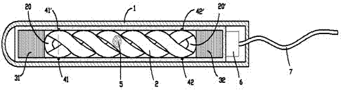
[0011] exist figure 1 In the shown embodiment, the concrete energy-saving vibrator includes a vibrating rod; the vibrating rod includes a shell 1 and an internal structure, and the internal structure includes a twisted tube 2 extending along the axis of the vibrating rod, and the twisted tube 2 The heads of the two sections of spiral tubes twisted in parallel are connected by a smooth conduit 20 , and the tails of the two sections of spiral tubes are also connected by a smooth conduit 20 ′, so that a smooth circulation channel is formed inside the twisted tube.

[0012] A free-rolling smooth steel ball 5 is provided in the circulation channel; a section of electromagnets 31, 32 coaxial with the twisted tube are respectively provided at both ends of the twisted tube; the electromagnets 31, 32 are coupled To the control module 6 located in the housing 1; the control module 6 is connected to an external power supply through a cable 7; the twisted tube 2, the electromagnets 31, 32...


PUM


Abstract

The invention provides an energy-saving concrete vibrating tamper which comprises a vibrating bar. The vibrating bar comprises a shell and an internal structure. The internal structure comprises a spiral tube extending along the axis of the vibrating bar. The head portions of two screw tubes in the spiral tube are connected through a smooth guide tube, and the tails of the two screw tubes are also connected through a smooth guide tube, so that a smooth circulation channel is formed inside the spiral tube, wherein the two screw tubes are twisted in parallel, and a steel ball is arranged in the smooth circulation channel. The two ends of the spiral tube are each provided with an electromagnet. The electromagnets are coupled to a control module in the shell. The control module is connected with an external power source through a cable. The spiral tube, the electromagnets and the control module are fixedly connected with the shell. The two ends of the spiral tube are provided with position sensors coupled to the control module. When one position sensor senses that the steel ball reaches the end, where the position sensor is located, of the spiral tube, the control module switches off the corresponding electromagnet at the end of the spiral tube, and the electromagnet at the other end of the spiral tube is switched on. The energy-saving concrete vibrating tamper is low in cost, small in energy consumption and low in noise, and has a good vibrating effect.

Description

technical field [0001] The invention relates to the field of building construction equipment, in particular to a concrete vibrator. Background technique [0002] In the field of building construction, in order to make the texture of the cast-in-place concrete uniform and remove the air bubbles in the concrete, it is necessary to vibrate the concrete after the pouring is completed; the basic equipment used in this process is a concrete vibrator. [0003] The traditional concrete vibrator includes an external motor, a flexible shaft and a vibrating rod; the vibrating rod has an eccentric rotating mechanism inside, and the eccentric rotating mechanism is driven by an external motor through a flexible shaft. The disadvantage is that the cost of the flexible shaft is high and the transmission efficiency Low energy consumption, high energy consumption; and the external motor is noisy, which seriously affects the surrounding environment, and is not conducive to the physical and m...

Claims


Application Information

Patent Timeline
Patent Type & Authority Applications(China)
IPC IPC(8): E04G21/08
Inventor 马人欢
Owner 浙江臻泰建设有限公司
Why Eureka
Try Eureka