

Power transmission tower
A technology of transmission tower and tower body, applied in the field of transmission tower, can solve problems such as poor torsional resistance of composite cross arms
- Summary
- Abstract
- Description
- Claims
- Application Information
AI Technical Summary
Problems solved by technology
Method used
Image

Examples
Embodiment 1
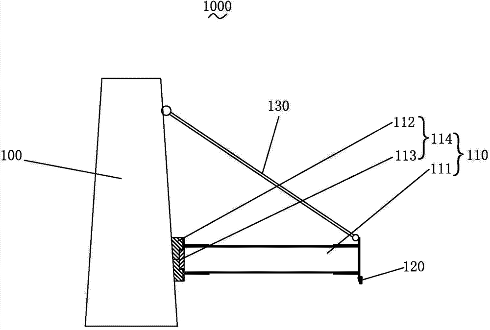
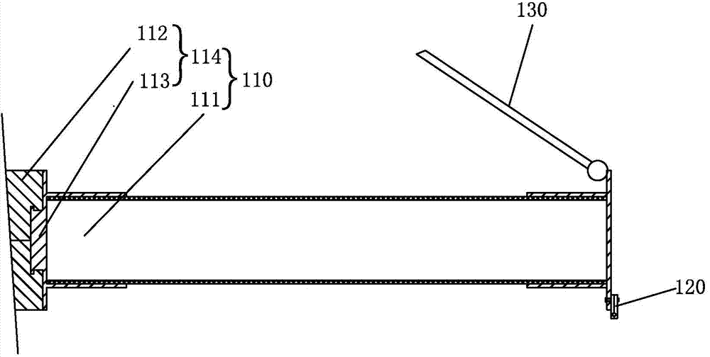
[0034] Such as figure 1 , figure 2 As shown, the power transmission tower 1000 of this embodiment includes a tower body 100 , a cross arm 110 is connected to the tower body 100 , and the end of the cross arm 110 is connected to a wire clamp fitting 120 . In addition, a cable stay 130 is also provided between the tower body 100 and the cross arm 110 . figure 1 , figure 2 In the figure, only the cross-arm 110 structure is cross-sectionally processed.
[0035] In this embodiment, the cross arm 110 is a composite cross arm, and the cross arm 110 includes an insulator 111 as a main body, and a rotating device 114 connected to one end of the insulator 111 . The rotating device 114 is fixed on the tower body 100 , and the insulator 111 is connected to the tower body 100 through the rotating device 114 . Wherein the insulator 111 is a hollow composite insulator, figure 1 , figure 2 It is only for illustration, and the shed structure outside the composite insulator is not draw...
Embodiment 2
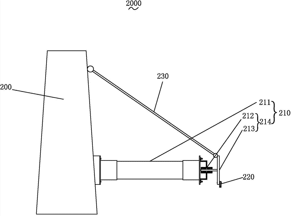
[0040] Such as image 3 , Figure 4 As shown, the power transmission tower 2000 of this embodiment includes a tower body 200 , a cross arm 210 is connected to the tower body 200 , and the end of the cross arm 210 is connected to a wire clamp fitting 220 . In addition, a cable stay 230 is also provided between the tower body 200 and the cross arm 210 .
[0041] In this embodiment, the cross arm 210 is a composite cross arm, and the cross arm 210 includes an insulator 211 as a main body, and a rotating device 214 connected to one end of the insulator 211 . The other end of the insulator 211 is fixed on the tower body 200 . The wire clip hardware 220 is connected to the rotating device 214 . Wherein the insulator 211 is a hollow composite insulator, image 3 , Figure 4 It is only for illustration, and the shed structure outside the composite insulator is not drawn.
[0042] The rotating device 214 includes a fixed cavity 212 fixed at the end of the insulator 211 and a movi...
Embodiment 3
[0046] Such as Figure 5 As shown, the structure of the transmission tower 3000 of this embodiment is basically the same as that of the transmission tower 2000 of the second embodiment of the present invention, the difference is that one end of the cable stay 330 is fixed on the tower body 300, and the other end is fixed on the insulator 311 away from the tower body 300 at one end. A limiting member 331 extends from the end of the cable-staying member 330 , one end of the limiting member 331 is fixed on the end of the cable-staying member 330 , and the other end is fixed on the moving shaft 313 .
[0047] In the transmission tower 3000 of this embodiment, the cable-stayed part 330 itself directly acts as the load-bearing insulator 311, and the angle of rotation of the stop shaft 313 is limited by the limiter 331, effectively preventing the cable-stayed part 330 from acting on the moving shaft 313 too much. The pulling force in the direction of the inclined stay member 330 pre...
PUM
 Abstract
Description
Claims
Application Information