Electric lifting mechanism

An electric lifting mechanism and electric push rod technology, which is applied to lifting devices, connecting components, mechanical equipment, etc., can solve the problems of inability to adjust the height of the LED screen light box, lack of lifting adjustment devices, and the lifting operation is not stable enough. The overall structure is compact and the appearance is simple

Inactive Publication Date: 2017-02-22
SHANGHAI NEW CENTURY ROBOT
View PDF5 Cites 0 Cited by
  • Summary
  • Abstract
  • Description
  • Claims
  • Application Information

AI Technical Summary

Problems solved by technology

[0002] At present, most of the LED screen light boxes used in the market cannot be adjusted in height, and lack special lifting adjustment devices.
However, some known lifting structures have the disadvantages of complex structure, difficult maintenance, high manufacturing cost, and uneven lifting operation.

Method used


Image

  • Electric lifting mechanism
  • Electric lifting mechanism
  • Electric lifting mechanism

Examples


Embodiment Construction

[0016] The present invention will be further described below in conjunction with the accompanying drawings.

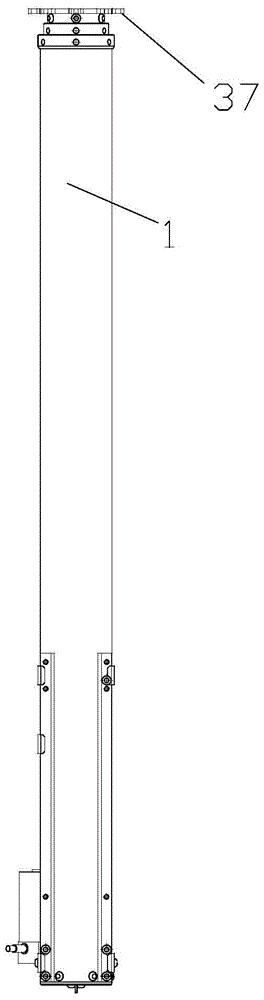
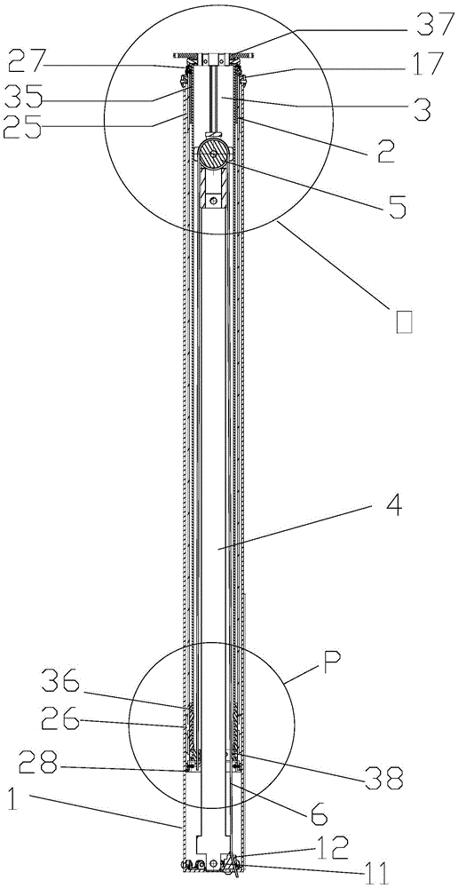
[0017] Please refer to Figure 1 to Figure 6 . An electric lifting mechanism according to an embodiment of the present invention includes a bushing, an electric push rod 4 , a pulley 5 and a wire rope 6 wound on the pulley 5 . The sleeve includes an outer tube 1 , a middle tube 2 and an inner tube 3 from outside to inside.

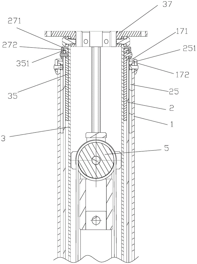
[0018] The bottom of the lumen of the outer tube 1 is provided with an electric push rod fixing part 11 and a wire rope fixing part 12 . The top of the lumen of the outer tube 1 is fixedly provided with an upper bushing 25 of the middle tube. A circle of flanging 251 is provided on the top of the upper bushing 25 of the middle pipe, and the bottom surface of the circle of flanging 251 of the middle pipe upper bush is pressed against the upper end surface of the outer pipe. The upper end of the outer pipe is fixedly provided with an outer pipe u...


PUM


Abstract

The invention discloses an electric lifting mechanism which comprises a sleeve pipe, an electric pushing rod, a pulley and a steel wire rope wound on the pulley. The sleeve pipe comprises an outer pipe, a middle pipe and an inner pipe from outside to inside in sequence. An electric pushing rod fixing part and a steel wire rope fixing part are arranged at the bottom of a pipe cavity of the outer pipe. A middle pipe upper lining sleeve is fixedly arranged at the top of the pipe cavity of the outer pipe. A middle pipe lower lining sleeve is arranged at the bottom of the middle pipe in a sleeved mode. An inner pipe upper lining sleeve is fixedly arranged at the top of a pipe cavity of the middle pipe. An inner pipe lower lining sleeve is arranged at the bottom of the inner pipe in a sleeved mode. An inner pipe lower flange is arranged at the lower end of the inner pipe. The inner pipe lower flange is placed below the inner pipe lower lining sleeve. The electric pushing rod comprises a pushing rod base and a pushing rod body. The pushing rod base is fixed on an electric pushing rod fixing part. The pulley is fixed at the top of the pushing rod. One end of the steel wire rope is fixed at a steel wire rope fixing part. The other end of the steel wire rope is connected with the inner pipe lower flange. The electric lifting mechanism is simple in structure, stable in lifting and operation and low in manufacturing cost.

Description

technical field [0001] The invention relates to a lifting mechanism, in particular to an electric lifting mechanism of a light box. Background technique [0002] At present, most of the LED screen light boxes used in the market cannot be adjusted in height, and lack special lifting adjustment devices. However, some known lifting structures have the disadvantages of complex structure, difficult maintenance, high manufacturing cost, and uneven lifting operation. Contents of the invention [0003] The technical problem to be solved by the present invention is to provide an electric lifting mechanism with simple structure, stable lifting operation and low manufacturing cost. [0004] In order to solve the problems of the technologies described above, the technical solution adopted in the present invention is: [0005] An electric lifting mechanism, including a casing, an electric push rod, a pulley and a steel wire rope wound on the pulley; the casing includes an outer tube,...

Claims


Application Information

Patent Timeline
Patent Type & Authority Patents(China)
IPC IPC(8): F16B7/10B66F11/00
CPCB66F11/00B66F2700/09
Inventor 张海峰吴家宸方继勇
Owner SHANGHAI NEW CENTURY ROBOT
Why Eureka
Try Eureka