Low and medium-pressure pneumatic balanced stop valve

A dynamic balancing and globe valve technology, applied in the direction of lift valve, valve details, valve device, etc., can solve the problems of misalignment of valve disc and valve seat axis, unstable valve body sealing contact, unstable sealing specific pressure, etc. Good sealing contact repeatability, tight and reliable sealing, lasting and stable sealing specific pressure

Inactive Publication Date: 2015-07-01
HUBEI HIGH & HIGH PRESSURE VALVE CO LTD
View PDF0 Cites 2 Cited by
  • Summary
  • Abstract
  • Description
  • Claims
  • Application Information

AI Technical Summary

Problems solved by technology

[0002] In the circulating water system of metallurgy, petroleum, electric power and other industries, the cooling water of the rolling mill, the laminar flow cooling water system, and the pre-flushing water supply system of high-pressure descaling water, the structure of the low and medium pressure pneumatic globe valve widely used at present is different. Perfect, there are the following deficiencies: 1. Most of the existing globe valves are cut-off structures. When the valve is opened and closed, the disc is pushed by the water medium, the operating torque is large, and the balance is poor; 2. The gap between the valve seat, the elastic gasket and the disc Between the piston rod and the valve rod is a separate floating connection structure, which causes the axes of the valve disc and the valve seat to not coincide. When moving up and down, it is shaken by the action of the water medium, and the sealing contact with the valve body is unstable, resulting in the sealing of the valve. Ineffective; 3. The valve disc has no guiding performance, and it will vibrate under the influence of the pressure fluctuation of the water medium, and the sealing specific pressure is unstable, so it is not suitable for occasions where the pressure is unstable; 4. The overall volume of the valve is large and the service life is short

Method used


Image

  • Low and medium-pressure pneumatic balanced stop valve

Examples


Embodiment Construction

[0011] Below in conjunction with accompanying drawing and specific embodiment the present invention is described in further detail:

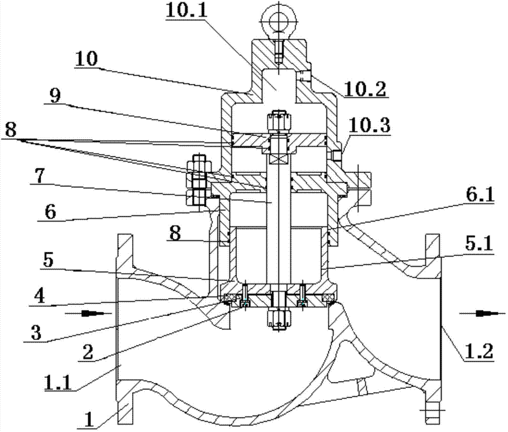
[0012] Such as figure 1 The low and medium pressure pneumatic balanced globe valve shown includes a valve body 1 with a water inlet channel 1.1 and a water outlet channel 1.2, a valve seat 3 is arranged above the valve body 1, and a valve seat 3 is arranged at the contact point of the valve body 1. Gasket 4, valve seat 3 is fixedly connected with valve disc 5, and also includes cylinder seat 6, the lower part of cylinder seat 6 is provided with guide platform 6.1, the upper part of valve disc 5 is provided with guide cylinder 5.1, and guide cylinder 5.1 is located on guide platform 6.1 Inside, the guide platform 6.1 and the guide cylinder 5.1 are sealed and socketed through the o-ring 8, the cylinder head 10 is placed on the cylinder seat 6, the cylinder seat 6 is located between the bottom end of the cylinder barrel 10 and the valve body 1, and...


PUM


Abstract

The invention relates to a low and medium-pressure pneumatic balanced stop valve which comprises a valve body provided with a water inlet channel and a water outlet channel, wherein a valve seat is arranged on the valve body; a sealing gasket is arranged at the contact part of the valve seat and the valve body; a valve clack is fixedly connected to the valve seat. The stop valve also comprises a cylinder seat and a cylinder barrel provided with an upper air source through hole and a lower air source through hole. A piston and a piston rod are arranged in the cylinder barrel. The bottom end of the cylinder barrel is fixedly connected with the valve body. One end of the piston rod is fixedly connected with the piston while the other end of the piston rod is fixedly connected with the valve seat. A guide platform is arranged below the cylinder seat. A guide barrel is arranged on the upper part of the valve clack. The guide platform and the guide barrel are in sealing cup joint. Under the conditions with any pressure difference of a water current medium, the opening and the closing of the stop valve are convenient, free, easy and labor-saving; the integral size of the valve is reduced; and the service life of the valve is prolonged.

Description

technical field [0001] The invention relates to circulating water in metallurgy, petroleum, electric power and other industries, as well as valves in the cooling water of rolling mills in rolling mills, laminar flow cooling water systems, and pre-flushing water supply systems for high-pressure descaling water. It is a low and medium pressure pneumatic balanced globe valve for passing and regulating water medium. Background technique [0002] In the circulating water system of metallurgy, petroleum, electric power and other industries, the cooling water of the rolling mill, the laminar flow cooling water system, and the pre-flushing water supply system of high-pressure descaling water, the structure of the low and medium pressure pneumatic globe valve widely used at present is different. Perfect, there are the following deficiencies: 1. Most of the existing globe valves are cut-off structures. When the valve is opened and closed, the disc is pushed by the water medium, the op...

Claims


Application Information

Patent Timeline
Patent Type & Authority Applications(China)
IPC IPC(8): F16K1/32F16K31/122F16K41/02
CPCF16K1/32F16K31/122
Inventor 张素珍靖金桃张长江罗凯张有才
Owner HUBEI HIGH & HIGH PRESSURE VALVE CO LTD
Why Eureka
Try Eureka