
Multi-cavity separated taking type vacuum drying box

A vacuum drying oven and multi-chamber technology, which is applied in the direction of drying solid materials, partial agitation dryers, dryers for static materials, etc., can solve the problems of affecting the drying effect of other materials and the large difference in drying temperature, and achieve the best drying effect Good, to avoid the effect of mutual influence

Inactive Publication Date: 2015-07-01
阿普瑞克(天津)环保塑材科技有限公司
View PDF0 Cites 3 Cited by
  • Summary
  • Abstract
  • Description
  • Claims
  • Application Information

AI Technical Summary

Problems solved by technology

The raw materials or semi-finished products of medicinal materials must go through the drying process to remove all or part of the water or solvent and meet the humidity requirements of the process before subsequent processing. Therefore, the performance of the drying box determines the drying quality of the medicinal materials; for pharmaceutical and chemical laboratories. In other words, the vacuum drying oven is an indispensable drying equipment, but because there are many varieties studied in the laboratory, the drying time and drying temperature of the products vary greatly, and it is often the case that a variety of materials are stored in a drying oven. At this time, if a material needs to be taken out, the air release valve of the box needs to be opened to restore the pressure in the whole box to a normal value before opening the box, which will definitely affect the drying effect of other materials in the box

Method used


Image

  • Multi-cavity separated taking type vacuum drying box
  • Multi-cavity separated taking type vacuum drying box

Examples


Embodiment Construction

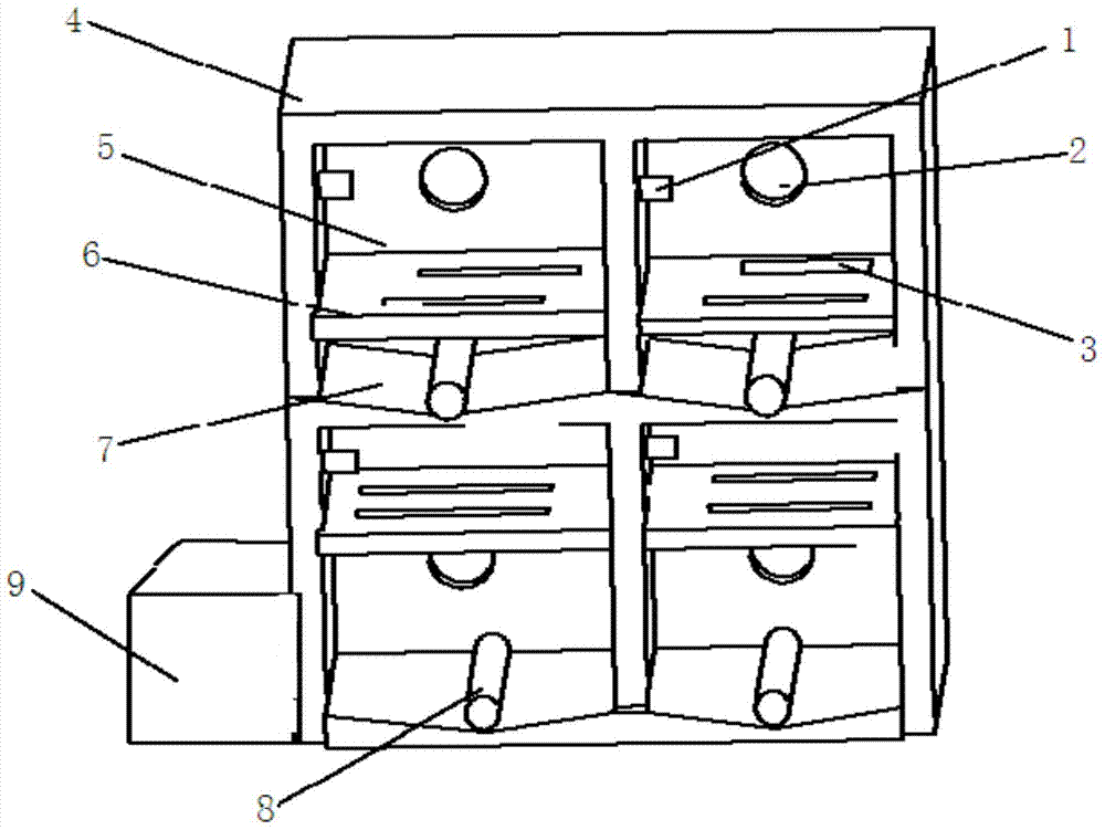
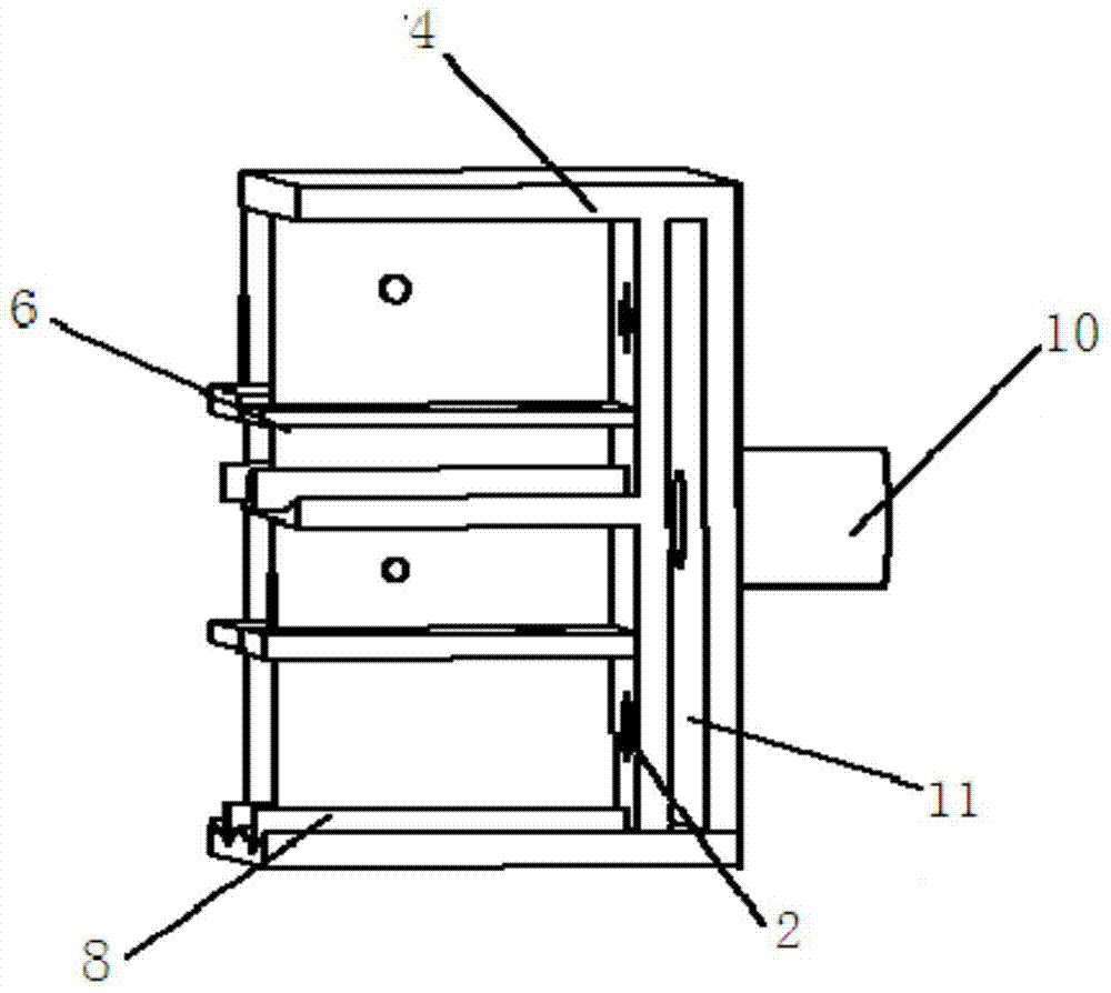
[0014] As shown in the figure, the present invention provides a multi-chamber split-type vacuum drying box, including a box body 4, an electric controller 9 and a vacuum pump (not shown in the figure), and the electric controller 9 and the vacuum pump are located outside the box body 4 , the internal space of the box body 4 is divided into a front material storage chamber and a rear vacuum chamber 11, and the rear vacuum chamber 11 is provided with an air release valve (not shown in the figure) and a vacuum connector 10 that can be connected to a vacuum pump;

[0015] The front material storage chamber is divided into four sub-chambers 5, and each sub-chamber 5 corresponds to a door (not shown in the figure). There is a switch control valve 2 on the rear side wall of the sub-chamber 5, and the sub-chamber 5 passes through The opening of the switch control valve 2 communicates with the rear vacuum chamber 11, and the sub-chamber 5 has a temperature and humidity sensor and a vacu...


PUM


Abstract

The invention provides a multi-cavity separated taking type vacuum drying box. The multi-cavity separated taking type vacuum drying box comprises a box body, an electric controller and a vacuum pump. The internal space of the box body is divided into a front material storage cavity and a rear vacuumizing cavity, and a deflation valve and a vacuum joint connected with the vacuum pump are arranged on the rear vacuumizing cavity; the front material storage cavity is evenly divided into four branched cavities, and switch control valves are arranged on the rear side walls of the branched cavities; the branched cavities are communicated with the rear vacuumizing cavity by opening the switch control valve. A temperature and humidity sensor and a vacuum degree sensor are arranged in each branched cavity, and a frame plate which is horizontally arranged and used for containing materials is arranged in each branched cavity and is of a hollow-out structure. The temperature and humidity sensors and the vacuum degree sensors are connected with the electric controller, and the vacuum pump, the deflation valve and the switch control valve are controlled by the electric controller. The multi-cavity separated taking type vacuum drying box has the beneficial effects that the structural design is reasonable, and the materials can be taken and put respectively.

Description

technical field [0001] The invention relates to a multi-chamber separating type vacuum drying oven. Background technique [0002] In the existing technical pharmaceutical industry, various dryers and drying ovens are very important equipment. The raw materials or semi-finished products of medicinal materials must go through the drying process to remove all or part of the water or solvent and meet the humidity requirements of the process before subsequent processing. Therefore, the performance of the drying box determines the drying quality of the medicinal materials; for pharmaceutical and chemical laboratories. In other words, the vacuum drying oven is an indispensable drying equipment, but because there are many varieties studied in the laboratory, the drying time and drying temperature of the products vary greatly, and it is often the case that a variety of materials are stored in a drying oven. At this time, if a material needs to be taken out, the air release valve of ...

Claims


Application Information

Patent Timeline
Patent Type & Authority Applications(China)
IPC IPC(8): F26B9/10F26B25/00
Inventor 刘焕如
Owner 阿普瑞克(天津)环保塑材科技有限公司
Learn More