
Sidelight backlight module and LGP (Light Guide Plate) thereof

A backlight module and side-light technology, which is applied in the field of side-light backlight modules and light guide plates, can solve problems such as light leakage, reduced LED heat dissipation performance, and poor brightness uniformity

Inactive Publication Date: 2015-07-01
FUTAIHUA PRECISION ELECTRONICS ZHENGZHOU +1
View PDF5 Cites 13 Cited by
  • Summary
  • Abstract
  • Description
  • Claims
  • Application Information

AI Technical Summary

Problems solved by technology

Among them, the direct-type backlight module directly places the light source under the light-emitting surface, which enhances the brightness of the light, but it is not conducive to the thin design of the backlight module; the side-light backlight module, the light source is placed on the side of the backlight module, The light beam emitted by the light source enters the light guide plate through the light incident surface of the light guide plate, and then exits from the light exit surface of the light guide plate
[0003] Generally, edge-lit backlight modules often use LEDs (Light-emitting Diodes, light-emitting diodes) as their backlight sources to make them have the characteristics of high brightness, narrow frame and thin profile. However, due to the small beam angle of LEDs, the light guide plate There is an area on the light-incident side with poor brightness uniformity and a wider frame on the light-incident side
At the same time, some researchers proposed that placing the LED light source under the light incident surface of the light guide plate reduces the thickness of the light incident side frame of the backlight module, but the above method will reduce the heat dissipation performance of the LED.
In addition, the above structure is prone to problems such as light leakage at the edge of the light incident side.

Method used


Image

  • Sidelight backlight module and LGP (Light Guide Plate) thereof
  • Sidelight backlight module and LGP (Light Guide Plate) thereof
  • Sidelight backlight module and LGP (Light Guide Plate) thereof

Examples


Embodiment Construction

[0017] An edge-lit backlight module provided by the present invention will be further described in detail below with reference to the accompanying drawings and embodiments.

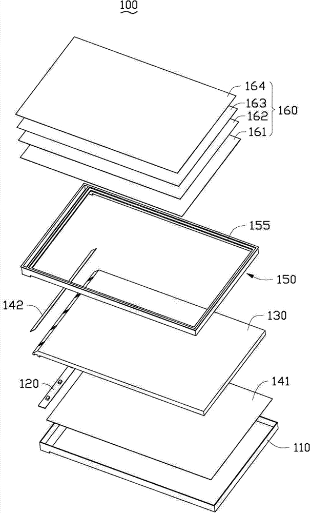
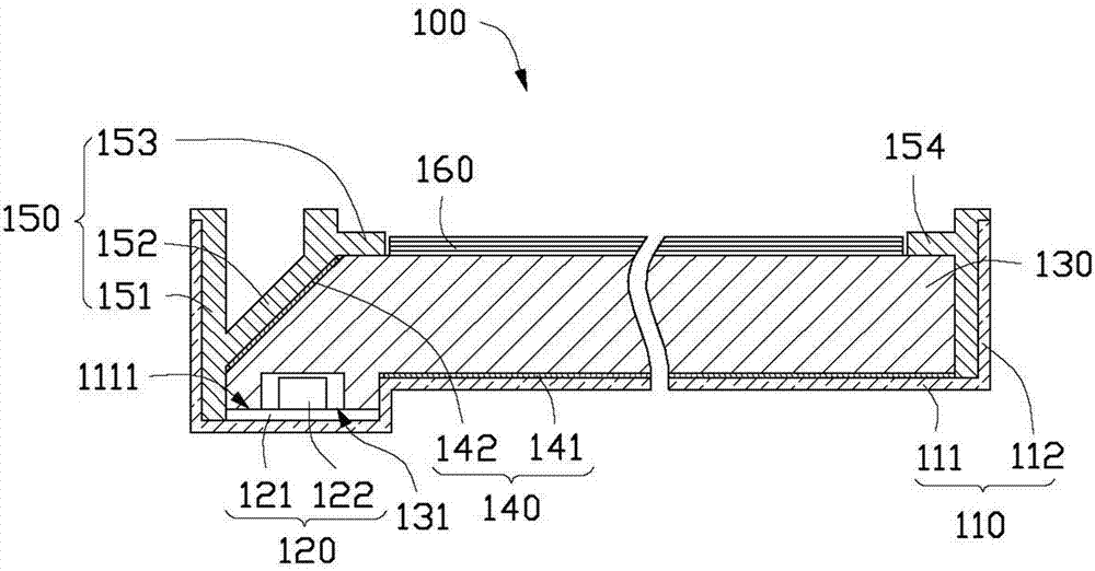
[0018] Please also see figure 1 and figure 2 Embodiment 1 of the present invention provides an edge-lit backlight module 100, including a back cover 110, an LED light source 120, a light guide plate 130 accommodated in the back cover 110, a reflective sheet 140, and a plastic frame set on the light guide plate 130 150 and optical sheet group 160.

[0019] The back cover 110 is made of metal sheet material, and includes a bottom plate 111 and a plurality of sidewalls 112 vertically extending from the edge of the bottom plate 111 to one side thereof. The bottom plate 111 is recessed with a groove 1111 adjacent to and parallel to the side wall 112 .

[0020] The LED light source 120 is strip-shaped and includes a substrate 121 and a plurality of LEDs 122 disposed on the substrate 121 . The LED light sou...


PUM


Abstract

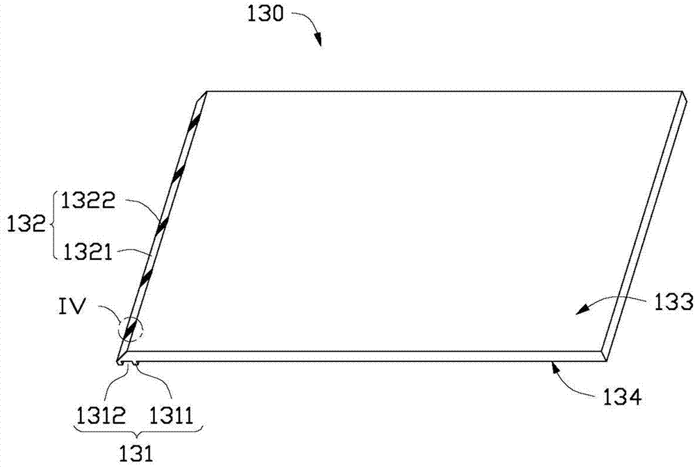
The present disclosure provides an edge-type backlight module including a back cover, a LED light source and a light guide plate. The back cover includes a bottom plate and a plurality of sidewalls. The LED light source with at least one LED is fixed on the bottom plate. The light guide plate is arranged in the back cover, which includes a light incident portion and a reflective portion. The reflective portion is obliquely arranged relative to the bottom plate of the back cover. The light incident portion defines a groove and is configured to receive the LED light source. The reflective potion includes a mirror-like reflective portion and a diffusion reflective portion. The diffusion reflective portion faces at least one LED.

Description

technical field [0001] The invention relates to a backlight module and its light guide plate, in particular to a side-light backlight module and its light guide plate. Background technique [0002] In recent years, liquid crystal displays have been greatly developed due to their lightness, thinness, small size and low power consumption. However, since the liquid crystal display device is a passive electronic display device, it cannot emit light by itself and needs a backlight module to display functions. The backlight module is divided into an edge-type backlight module and a direct-type backlight module according to the position of the light source. Among them, the direct-type backlight module directly places the light source under the light-emitting surface, which enhances the brightness of the light, but it is not conducive to the thin design of the backlight module; the side-light backlight module, the light source is placed on the side of the backlight module, The lig...

Claims


Application Information

Patent Timeline
IPC IPC(8): G02F1/13357G02B6/00F21V8/00F21Y101/02
CPCG02B6/0021G02B6/0031G02B6/0073G02F1/133615G02F1/133607G02B6/0018
Inventor 章绍汉
Owner FUTAIHUA PRECISION ELECTRONICS ZHENGZHOU
Learn More