Manufacturing method of metal grid conductive film, metal grid conductive film and touch panel

A technology of metal grid and manufacturing method, applied in the direction of electrical digital data processing, input/output process of data processing, instruments, etc., can solve the problems of high ITO resistance, high cost, poor flexibility, etc., and achieve high response speed , enhanced adhesion, low resistance effect

Active Publication Date: 2018-02-13
SHENZHEN SUCCESS ELECTRONICS LTD
View PDF7 Cites 1 Cited by
  • Summary
  • Abstract
  • Description
  • Claims
  • Application Information

AI Technical Summary

Problems solved by technology

[0002] At present, most capacitive touch panels use the ITO (indium tin oxide) conductive film with mature production technology, but the ITO conductive film has its insurmountable shortcomings: the resistance of ITO is high, and it is not suitable for making medium and large size touch panels; ITO is fragile and has poor flexibility, which is not conducive to the production of flexible panels; high sputtering temperature can easily cause damage to the plastic film and limit the process
The metal film photolithography method first forms a layer of metal film on a transparent substrate by sputtering process or metal foil bonding, and then obtains a fine metal grid through steps such as photoresist coating, exposure, development, etching and stripping. The method has many steps, serious waste of metal materials, high cost, and great environmental pollution; the nano-metal ink printing method is achieved by inkjet printing (Inkjet Printing), aerosol-jet printing (Aerosol-Jet Printing) or gravure printing (Gravure Printing), etc. The method is to print nano-metal ink on a transparent substrate and sinter it. This method minimizes the waste of materials, but this method has high requirements on the stability of the ink, and it is difficult to obtain a metal grid with a line width of less than 30 microns; nano-metal The principle of the ink self-assembly method is to apply nano-metal ink to the substrate, and use the hydrophilic / hydrophobic interaction between the solution and the substrate to self-assemble to form an irregularly shaped metal grid. This metal grid is conducive to Eliminate moiré, but it is difficult to control the shape of the pattern. If it is to be applied on a touch screen, it is still necessary to perform patterning on the metal grid by laser etching or chemical etching; The groove network pattern is embossed on the substrate, and then the nano-metal ink is filled into the groove network through precise coating, and finally solidified into a metal grid. This method can improve the metal grid's easy scratch and weak adhesion to the substrate However, it is difficult to accurately fill the nano-metallic ink into the groove to ensure the continuous line and remove the residual nano-metallic ink outside the groove; the silver salt emulsion development method uses silver halide film, after exposure, development and fixing Form a silver metal grid pattern. This method has flexible grid pattern design and low cost, but the process is still relatively complicated

Method used


Image

  • Manufacturing method of metal grid conductive film, metal grid conductive film and touch panel
  • Manufacturing method of metal grid conductive film, metal grid conductive film and touch panel
  • Manufacturing method of metal grid conductive film, metal grid conductive film and touch panel

Examples


Embodiment 1

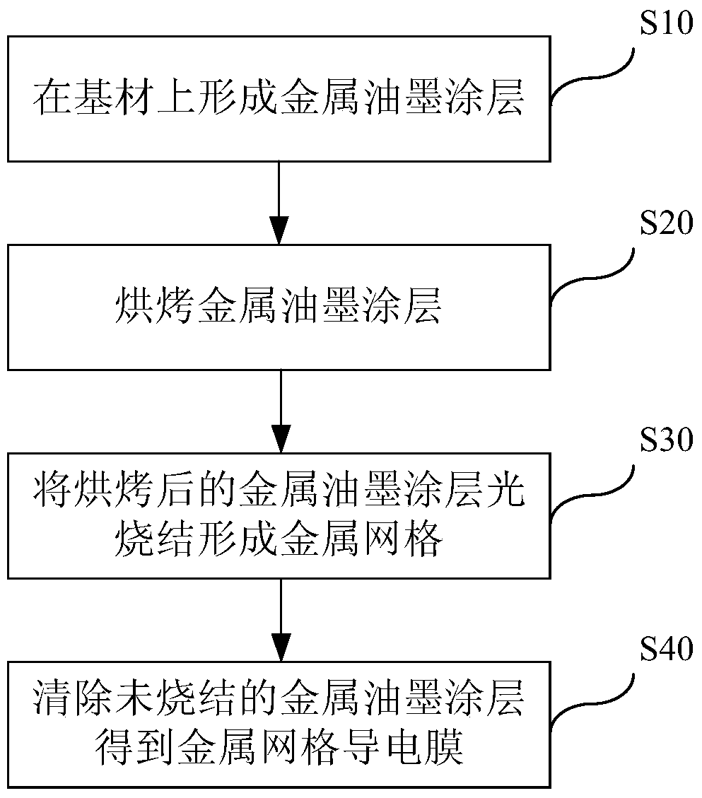
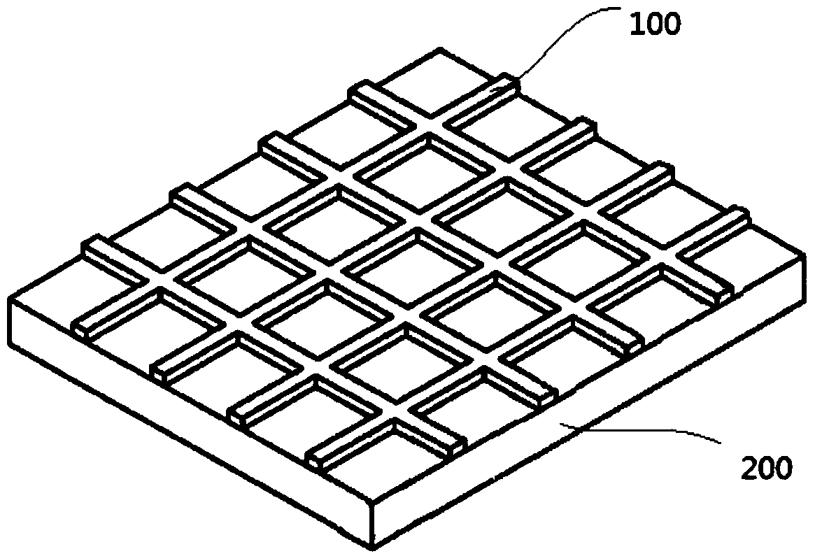
[0054] The manufacturing method of the metal grid conductive film provided in this embodiment includes the following steps:

[0055] S10: forming a metallic ink coating on the substrate.

[0056] Prepare the nano-copper ink coating and CPI film (transparent polyimide film), and apply the nano-copper ink to the CPI film by slit coating. The nano-copper ink coating is composed of copper nanoparticles (average particle size is 45nm), dispersant (manufactured by HUNTSMAN Company of the United States), 1,2-propanediol and propylene glycol monobutyl ether, wherein the content of copper nanoparticles is about 20wt%. The thickness of the CPI film is 50 μm.

[0057] S20: Baking the metallic ink coating.

[0058] Transfer the CPI film coated with nano-copper ink to a hot air drying oven and bake at 100°C for 30 minutes to remove the solvent, and obtain a layer of nano-copper ink coating with a dry film thickness of about 1 μm on the surface of the CPI film.

[0059] S30: Photo-sint...

Embodiment 2

[0064] The manufacturing method of the metal grid conductive film provided in this embodiment includes the following steps:

[0065] S10: forming a metallic ink coating on the substrate.

[0066] Prepare the nano-copper ink coating and the CPI film, and apply the nano-copper ink to the CPI film by spin coating. The nano-copper ink coating is composed of copper nanoparticles (average particle size is 45nm), dispersant (manufactured by HUNTSMAN Company of the United States), 1,2-propanediol and propylene glycol monobutyl ether, wherein the content of copper nanoparticles is about 20wt%. The thickness of the CPI film is 50 μm.

[0067] S20: Baking the metallic ink coating.

[0068] Transfer the CPI film coated with nano-copper ink to a hot air drying oven and bake at 80°C for 30 minutes to remove the solvent, and obtain a layer of nano-copper ink coating with a dry film thickness of about 0.5 μm on the surface of the CPI film.

[0069] S30: Photo-sintering the baked metal in...

Embodiment 3

[0074] The manufacturing method of the metal grid conductive film provided in this embodiment includes the following steps:

[0075] S10: forming a metallic ink coating on the substrate.

[0076] Prepare the nano-silver ink coating and the PEN film, and apply the nano-silver ink to the PEN film by slit coating. Nano-silver ink coating consists of silver nanoparticles (average particle size is 20nm), dispersant (manufactured by U.S. HUNTSMAN company), 1,2-propanediol and propylene glycol monobutyl ether, wherein the content of silver nanoparticles is about 20wt%. The thickness of the PEN film was 188 μm.

[0077] S20: Baking the metallic ink coating.

[0078] Transfer the PEN film coated with nano-silver ink to a hot air drying oven and bake at 80°C for 30 minutes to remove the solvent, and obtain a layer of nano-silver ink coating with a dry film thickness of about 2 μm on the surface of the PEN film.

[0079] S30: Photo-sintering the baked metal ink coating to form a met...


PUM

PropertyMeasurementUnit
thicknessaaaaaaaaaa
particle diameteraaaaaaaaaa
widthaaaaaaaaaa

Abstract

The invention discloses a method for manufacturing a metal grid conductive film, comprising: forming a metal ink coating on a base material; baking the metal ink coating; and sintering the baked metal ink coating to form Metal grid; removing the unsintered metal ink coating to obtain a metal grid conductive film. The invention also discloses a metal grid conductive film and a touch panel. The manufacturing method of the metal grid conductive film of the present invention has simple process and low cost, and can prepare a flexible patterned metal grid conductive film and a touch panel.

Description

technical field [0001] The invention belongs to the technical field of touch screen manufacturing, and in particular relates to a method for manufacturing a metal grid conductive film for a touch screen, a metal grid conductive film produced by the method, and a touch panel using the metal grid conductive film. Background technique [0002] At present, most capacitive touch panels use the ITO (indium tin oxide) conductive film with mature production technology, but the ITO conductive film has its insurmountable shortcomings: the resistance of ITO is high, and it is not suitable for making medium and large size touch panels; ITO is fragile and has poor flexibility, which is not conducive to the production of flexible panels; high sputtering temperature can easily cause damage to the plastic film and limit the process. [0003] Metal mesh transparent conductive film (Metal Mesh) has the advantages of low resistance, fast response speed, and good flexibility. It is especially s...

Claims


Application Information

Patent Timeline
Patent Type & Authority Patents(China)
IPC IPC(8): G06F3/041G06F3/044
Inventor 莫志源杨顺林龙集贤廖昌
Owner SHENZHEN SUCCESS ELECTRONICS LTD
Why Eureka
Try Eureka