Terminal Connection Structure

A terminal and structure technology, applied in the direction of connection, conductive connection, structural connection, etc., to achieve the effect of easy connection operation, increased volume, and a wide range of options

Active Publication Date: 2018-06-08
ORMON CORP
View PDF7 Cites 0 Cited by
  • Summary
  • Abstract
  • Description
  • Claims
  • Application Information

AI Technical Summary

Problems solved by technology

In addition, there is a problem that intermediate products of the single-phase induction motor 100 having different relay terminal connection structures must be stocked for each customer.

Method used


Image

  • Terminal Connection Structure
  • Terminal Connection Structure
  • Terminal Connection Structure

Examples


Embodiment Construction

[0106] according to Figure 1 to Figure 26 The accompanying drawings illustrate the connection structure of the terminal of the present invention.

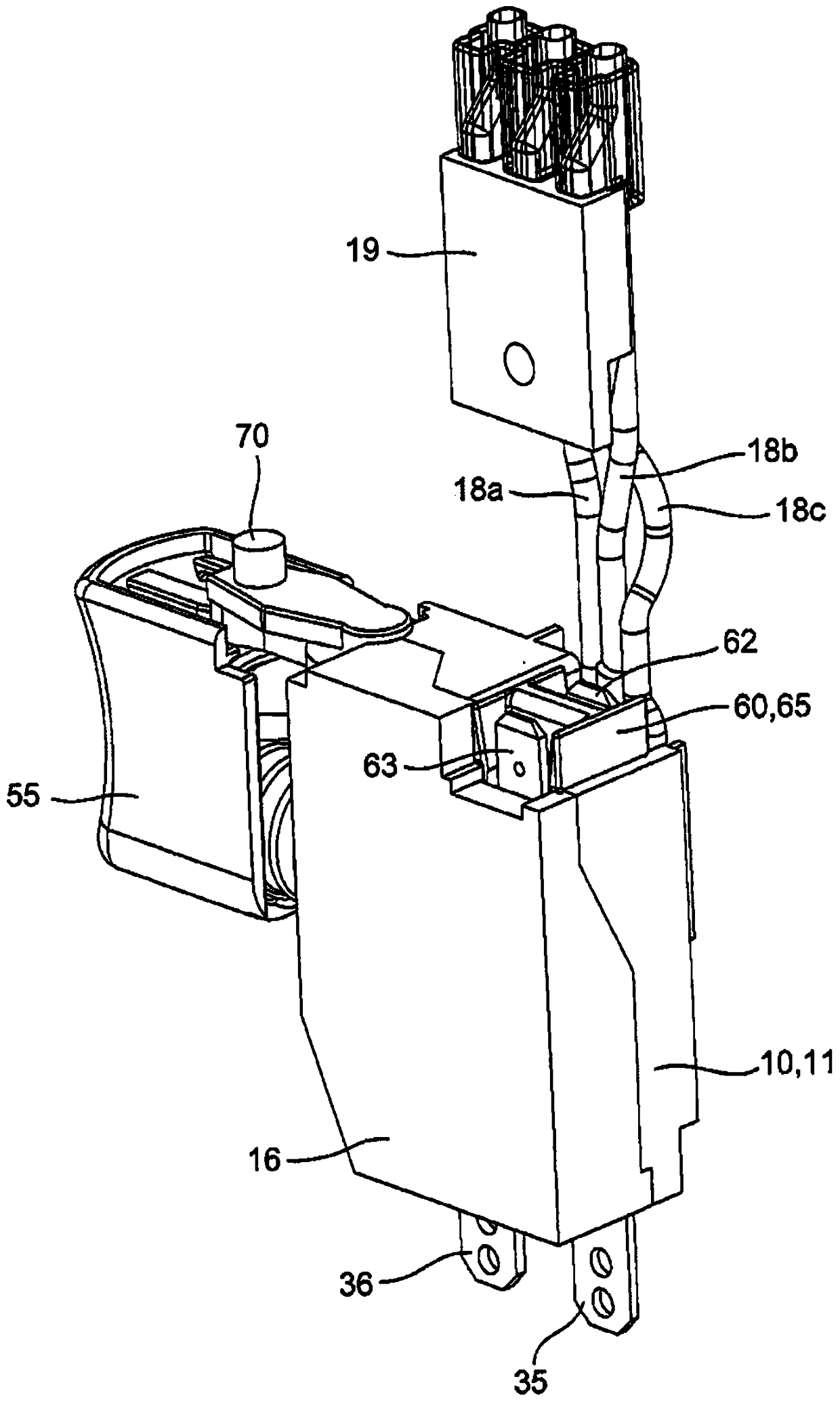
[0107] Such as Figure 1 to Figure 10 As shown, the terminal connection structure of the first embodiment is applicable to the case of a trigger switch for an electric tool, in particular, the case of unitizing the joint terminal for a motor protruding upward.

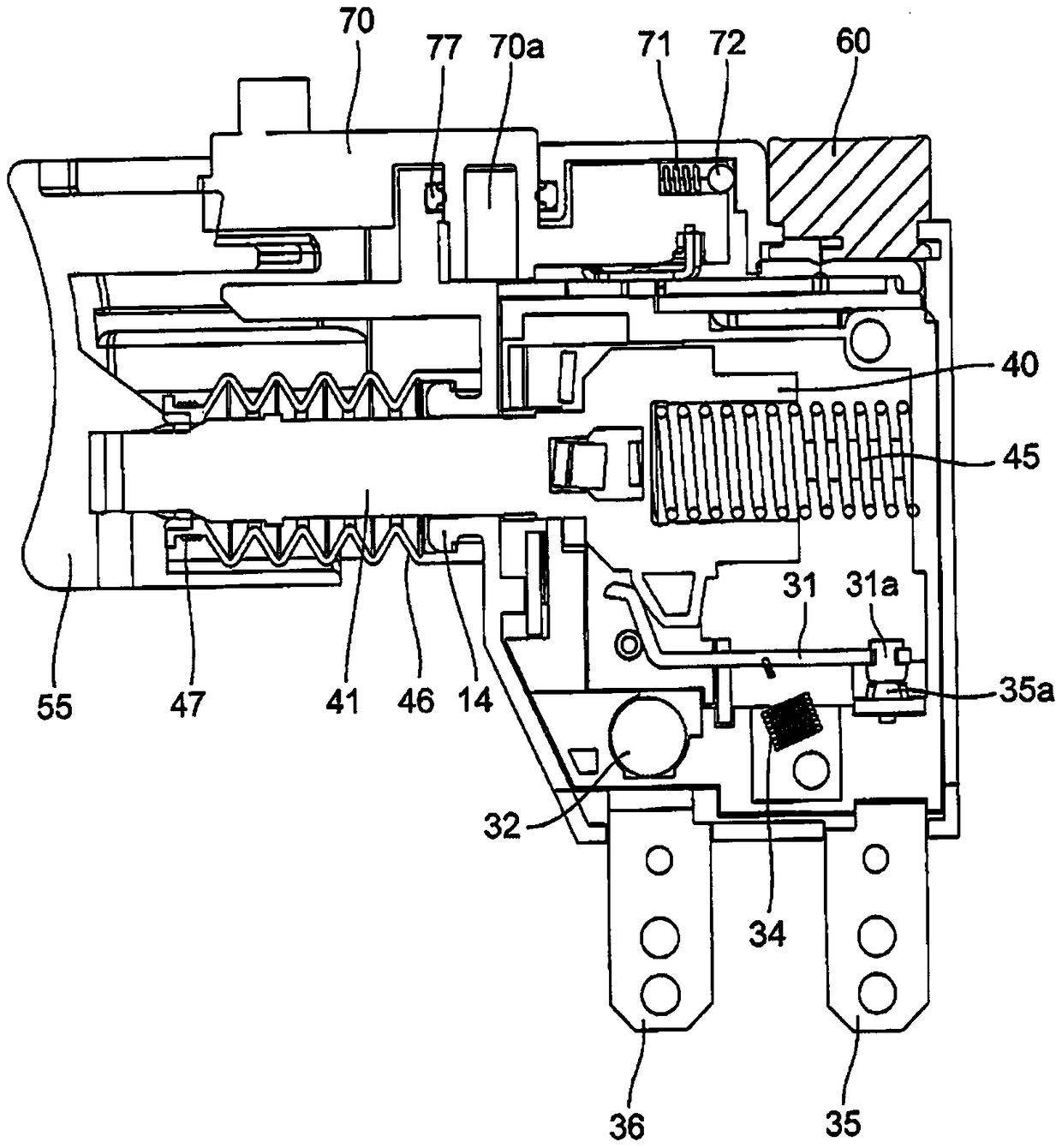
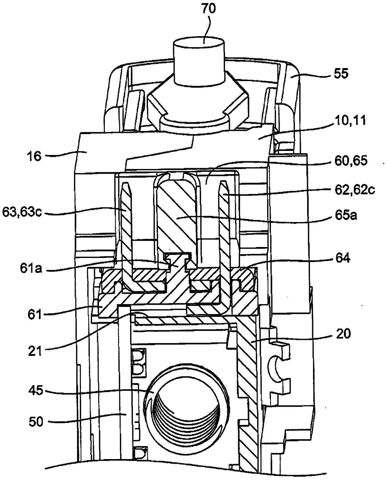
[0108] That is, if Figure 4 and Figure 5 As shown, the above-mentioned trigger switch is assembled in the housing 10 formed by combining the first cover 11 and the second cover 16, and the internal components such as the base body 20, the plunger 40, and the printed circuit board 50 are assembled, and the trigger 55 and the terminal unit are assembled. 60 and operating rod 70. In addition, a socket 19 is connected to internal components such as the printed circuit board 50 through lead wires 18a, 18b, and 18c.

[0109] Such as Figure 4 As shown, the first cover 11...


PUM


Abstract

The present invention provides a connection structure of a terminal capable of supporting various connection methods. In this terminal connection structure, a pair of joint terminals (62, 63) is provided on the base body (20) accommodated in the casing, and the pair of terminal parts (62c, 62c, 63c) are exposed from the case so as to be individually connectable to external terminals. Therefore, the terminal unit (60) disposed so that the terminal board (61) is sandwiched between the pair of joint terminals (62, 63) can be replaced on the base body (20).

Description

technical field [0001] The present invention relates to a connection structure of a terminal, for example, a connection structure of a relay terminal of an electric tool. Background technique [0002] At present, as the connection structure of the relay terminal of the electric tool, there is a positive characteristic thermistor connected in series with the auxiliary winding and a socket terminal electrically connected to the detachable connecting pin, which is composed of the main winding and the auxiliary winding. The starter device for a single-phase induction motor of the present invention, wherein the socket terminal is formed such that a pair of plate portions extending laterally in the axial direction of the connecting pin are bent inwardly so that the front end can conform to the cylindrical shape of the connecting pin. The connecting pin holding part is arc-shaped and separated from each other at the front end, and the connecting pin holding part is divided into a f...

Claims


Application Information

Patent Timeline
Patent Type & Authority Patents(China)
IPC IPC(8): H01R13/20
CPCH01H13/06H01R2201/10H02K5/225H02K7/145H01H2009/065H02K11/28H01R4/4809H01R13/436H01R13/514H01R9/18H01H9/061H01H9/063H01R9/16
Inventor 小山泰基小林实保住昭宏
Owner ORMON CORP
Why Eureka
Try Eureka