
Power calibration method and system for radio frequency receiver of terminal

A radio frequency receiver, power calibration technology, applied in the field of communication, can solve the problems of low calibration efficiency, long calibration time, and many frequency bands, and achieve the effect of improving calibration efficiency

Active Publication Date: 2015-07-01
SPREADTRUM COMM (SHANGHAI) CO LTD
View PDF3 Cites 7 Cited by
  • Summary
  • Abstract
  • Description
  • Claims
  • Application Information

AI Technical Summary

Problems solved by technology

[0004] However, since the LTE system includes two types of time division duplex and frequency division duplex, and there are many frequency bands, it is necessary to select a large number of calibration frequency points and test signals corresponding to the calibration power for calibration. The calibration time is long and the calibration efficiency is low.

Method used


Image

  • Power calibration method and system for radio frequency receiver of terminal
  • Power calibration method and system for radio frequency receiver of terminal
  • Power calibration method and system for radio frequency receiver of terminal

Examples


Embodiment Construction

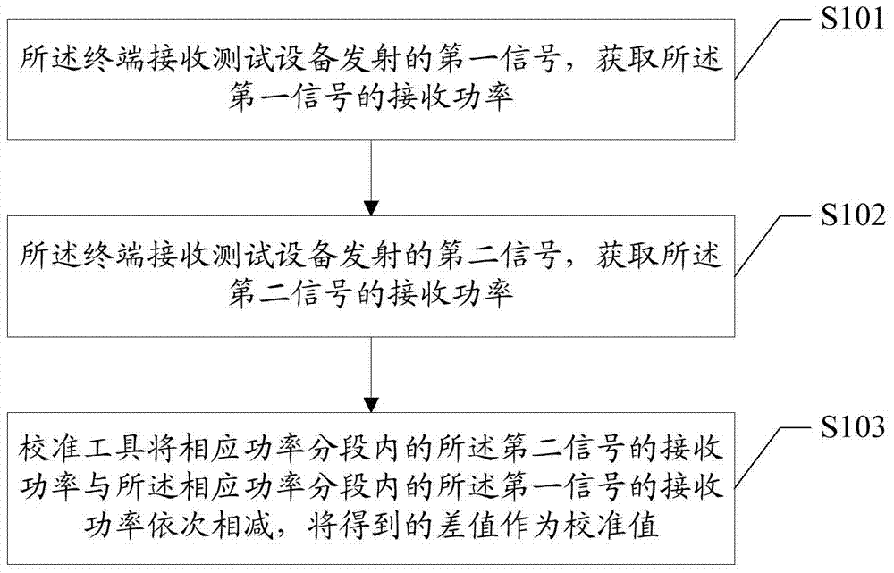
[0033] In the prior art solution, the calibration device sends a calibration command to the test device and the LTE terminal; the test device transmits a test signal corresponding to the power of the corresponding frequency point according to the calibration command; the LTE terminal receives the test signal and obtains the power value of the test signal, And send the power value of the test signal to the calibration tool; the calibration tool uses the power of the test signal sent by the test equipment to perform calculations with the signal power value obtained by the LTE terminal, and saves the calculation result as a calibration value. Then issue the next calibration command, and repeat the above operation steps until the calibration power calibration corresponding to all frequency points to be calibrated is completed. The above solution needs to select a large number of calibration frequency points and test signals corresponding to the calibration power for calibration, th...


PUM


Abstract

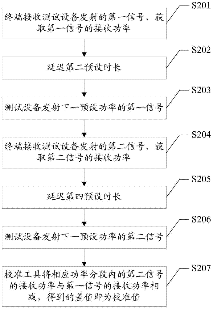
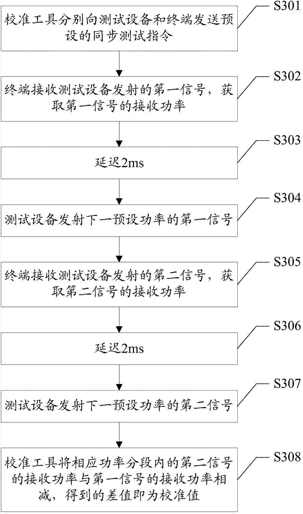
The invention discloses a power calibration method and system for a radio frequency receiver of a terminal. The power calibration method for the radio frequency receiver of the terminal includes that the terminal receives a first signal emitted from test equipment and acquires the received power of the first signal; the terminal receives a second signal emitted from the test equipment and acquires the received power of the second signal; a calibration tool subtracts the received power of the second signal in the corresponding power section and the received power of the first signal in the corresponding power section in sequence, and the difference value is used as the calibration value. The method and system are capable of effectively improving the power calibration efficiency for the radio frequency receiver of the terminal.

Description

technical field [0001] The invention relates to the field of communication technology, in particular to a power calibration method and system for a terminal radio frequency receiver. Background technique [0002] Long Term Evolution (LTE) is the long-term evolution of the general mobile communication system technology led by the 3rd Generation Partnership Project (3GPP), and is currently a widely recognized wireless communication technology. [0003] When the wireless communication chip of the LTE terminal is mass-produced, the receiver of the radio frequency chip needs to be calibrated. In the prior art solution, calibration equipment, testing equipment and LTE terminal can be used to complete the calibration together, and the power calibration of the receiver of the radio frequency chip can be performed through the following steps: the calibration equipment sends a calibration instruction to the testing equipment and the LTE terminal; Command, transmit the test signal of ...

Claims


Application Information

Patent Timeline
IPC IPC(8): H04B1/10
Inventor 薛丰廷侯庆柱
Owner SPREADTRUM COMM (SHANGHAI) CO LTD
Learn More