Gear part shaving fixture

A technology of parts and fixtures, which is applied in the field of shaving fixtures for gear parts, can solve the problems of gear tooth profile difference and large positioning gap, etc., and achieve the effects of low cost, improved precision and simple structure

Inactive Publication Date: 2015-07-08
CHINA NAT HEAVY DUTY TRUCK GROUP DATONG GEARCO
View PDF6 Cites 1 Cited by
  • Summary
  • Abstract
  • Description
  • Claims
  • Application Information

AI Technical Summary

Problems solved by technology

[0003] In order to solve the problem that the existing tooling for gear parts uses a light hole for centering, there is a large positioning gap, resulting in a poor gear tooth shape and tooth direction, and provides a gear part shaving processing jig

Method used


Image

  • Gear part shaving fixture

Examples


Embodiment Construction

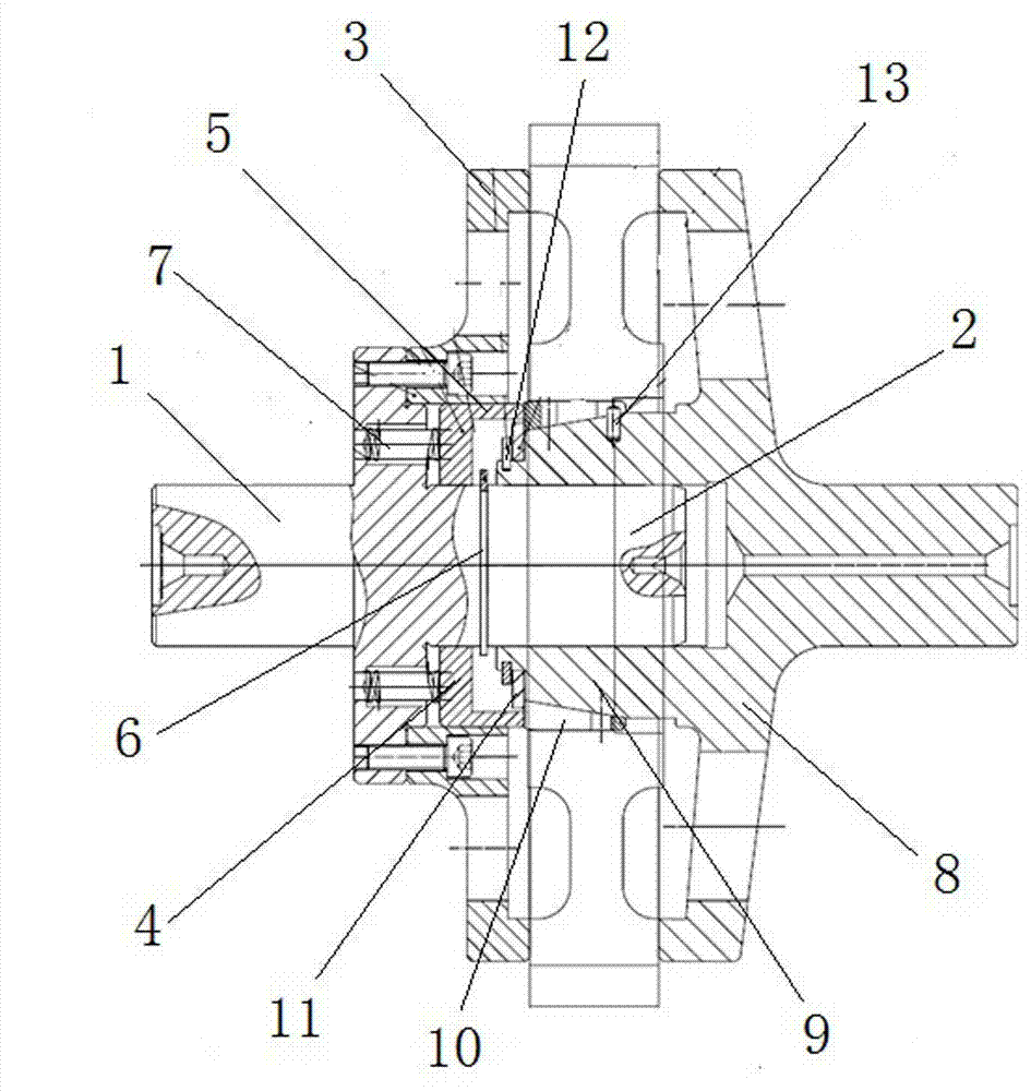
[0009] Gear parts shaving fixture, including the left spindle assembly and the right spindle assembly arranged between the left and right tops of the gear shaving machine; the left spindle assembly includes a stepped left base 1, the center of which is fixed There is a mandrel body 2, a hollow left positioning seat 3 is connected to the right end of the left base 1, a pressure pad 4 is arranged in the left positioning seat 3, a pressure ring 5 is provided on the right side of the edge of the pressure pad 4, and a pressure ring 5 is provided on the mandrel body 2. The left snap spring 6 on the right side of the pad 4, the tension spring 7 in contact with the pressure pad 4 is arranged in the left base 1; the right spindle assembly includes a stepped right positioning seat 8, and the left end surface of the right positioning seat 8 is provided with The tapered sleeve 9 is set on the mandrel body 2. The slope of the tapered sleeve 9 is covered with a spring sleeve 10 corresponding...


PUM


Abstract

The invention specifically discloses a gear part shaving fixture which solves the problems that due to the fact that an existing tool for a gear part is large in positioning gap during unthreaded hole centering, a gear is poor in tooth shape and tooth direction. The gear part shaving fixture comprises a left mandrel assembly and a right mandrel assembly. The left mandrel assembly comprises a left base. A mandrel body is fixed to the center of the left base. The right end of the left base is connected with a hollow left positioning base. A pressing cushion is arranged in the left positioning base. A pressing ring is arranged on the right side of the edge of the pressing cushion. A left snap spring is arranged on the mandrel body. A tension spring is arranged in the left base. The right mandrel assembly comprises a stepped right positioning base. A conical sleeve is arranged on the left end face of the right positioning base. The inclined face of the conical sleeve is sleeved with a spring sleeve. The conical sleeve is sleeved with a limiting cushion. A right snap spring is arranged at the left end of the limiting cushion. A limiting pin is arranged on the right side of the spring sleeve. The problem that displacement is prone to happening when force is borne in the axial direction is solved, the turning difficulty is lowered, and the shaving accuracy is improved.

Description

technical field [0001] The invention relates to gear part processing tooling, in particular to a gear part shaving processing jig. Background technique [0002] The existing gear parts shaving fixture adopts light hole centering, because the size of the inner hole fluctuates during turning. When the inner hole size deviates, the positioning gap is too large, resulting in poor gear tooth shape and direction, which affects the gear shaving accuracy. Contents of the invention [0003] In order to solve the problem that existing tooling for gear parts uses a light hole for centering and there is a large positioning gap resulting in poor gear tooth shape and tooth direction, the invention provides a gear part shaving processing jig. [0004] The present invention is realized by adopting the following technical solutions: the gear parts gear shaving fixture includes a left mandrel assembly and a right mandrel assembly arranged between the left and right tops of the gear shaving ...

Claims


Application Information

Patent Timeline
Patent Type & Authority Applications(China)
IPC IPC(8): B23F23/06
Inventor 师公飞党平任敏朱昆夏康康段鹏李国强郭文凯雷鹏宇
Owner CHINA NAT HEAVY DUTY TRUCK GROUP DATONG GEARCO
Why Eureka
Try Eureka