self-propelled hydraulic mixer

A kind of mixer, self-propelled technology, applied in the direction of cement mixing device, clay preparation device, unloading device, etc., can solve problems such as uneven distribution, affecting mixing efficiency and mixing uniformity, and achieve the effect of ensuring mixing efficiency

Active Publication Date: 2017-05-31
CHONGQING HONGGONG INSTRUCTIONAL MACHINE
View PDF10 Cites 2 Cited by
  • Summary
  • Abstract
  • Description
  • Claims
  • Application Information

AI Technical Summary

Problems solved by technology

For example, the patent application number 201420092909.X discloses a batching and mixing vehicle-mounted pump. Two parts, the automatic batching and stirring mechanism and the pumping main body, are installed on the chassis of the car, and the bracket of the automatic batching and stirring mechanism is fixed on the pumping main body with bolts. , the pumping main body is located under the automatic batching and mixing mechanism and fixed on the chassis of the car. It is a self-propelled automatic batching and mixing vehicle-mounted pump that integrates continuous automatic batching, forced mixing, concrete pumping, spraying and other functions, but its The disadvantage is that the pumping main body is fixed on the chassis of the car, and the stirring mechanism is fixed on the pumping main body, so that the position of the stirring mechanism on the car cannot be adjusted. It is in an inclined shape, which leads to uneven distribution of materials in the mixing tank, and it is easy to accumulate towards the lower end of the mixing tank, so that the materials cannot be fully stirred and mixed by the stirring arm or other stirring actuators in the mixing tank, which affects the mixing efficiency and mixing. Uniformity

Method used


Image

  • self-propelled hydraulic mixer
  • self-propelled hydraulic mixer
  • self-propelled hydraulic mixer

Examples


Embodiment 1

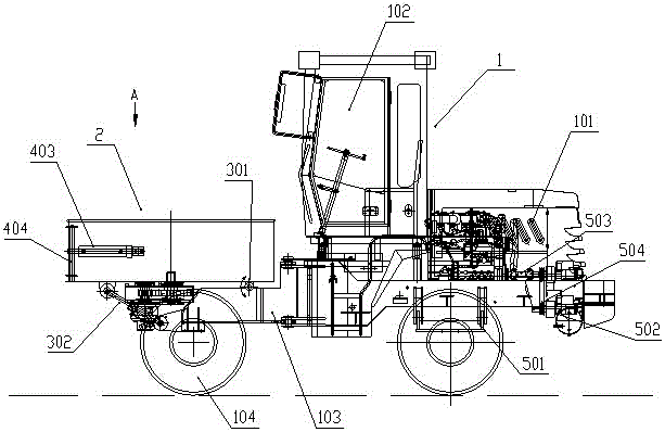
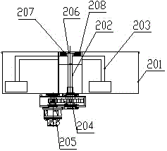
[0022] Such as Figure 1-4 Shown: the self-propelled hydraulic mixer of this embodiment includes a movable car body 1 and a mixer 2 installed on the car body, wherein: the car body 1 includes an operating room 102, a vehicle frame 103 and tires 104, in this embodiment The car body is refitted by removing the bucket from a wheel loader; the mixer 2 includes a mixing bucket 201, a mixing shaft 202 coaxially arranged in the mixing bucket, a mixing arm 203 uniformly distributed on the mixing shaft in the circumferential direction, and a mixing arm 203 installed in the mixing bucket 201. The lower gearbox 204 and the hydraulic motor 205 driving the gearbox 204, the stirring shaft 202 passes through the bottom of the mixing drum 201 and is connected to the output shaft of the gearbox 204, and the hydraulic motor 205 drives the stirring shaft 202 through the gearbox 204 And the stirring arm 203 rotates, and the rotating stirring arm 203 completes the stirring of materials such as con...

Embodiment 2

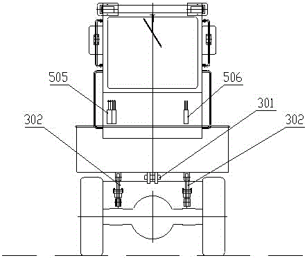
[0029] The first swing cylinder 302 in Embodiment 1 and the rotating horizontal shaft 301 of the mixer 2 are directly installed on the vehicle frame of the vehicle body. Such as Figure 7 As shown, the difference from Embodiment 1 is that this embodiment also includes a swing frame 601 located on the vehicle body frame, the mixer 2 and the first swing cylinder 302 are installed on the swing frame 601, correspondingly, the mixer 2 The horizontal axis 301 of rotation is also located on the swing frame 601; the swing frame 601 is hinged with the vehicle frame of the vehicle body 1 around the vertical axis 602 perpendicular to the vehicle axis, and is driven by the second swing cylinder 603 positioned on the vehicle body frame Pivot around this longitudinal axis 602 . When the car body 1 is on a left-right uneven road surface, the second swing cylinder 603 drives the swing frame 601 and the mixer 2 on the swing frame to swing around the longitudinal axis 602, and the position of ...


PUM


Abstract

A self-propelled hydraulic agitator is disclosed. The hydraulic agitator comprises a movable vehicle body and an agitator mounted on the vehicle body. The agitator can rotate around a horizontal shaft parallel to the vehicle shaft of the vehicle body, and is driven to swing around the horizontal shaft by first swing cylinders on the vehicle body. When the vehicle body works on a slope, the agitator is driven to swing by the first swing cylinders, and the axial position of the agitator can be adjusted to ensure that the agitator is not inclined at the axial direction, thus effectively ensuring the agitating efficiency of the agitator.

Description

technical field [0001] The invention relates to a self-propelled hydraulic mixer. Background technique [0002] The vehicle-mounted mixer is a device that installs the mixer on the car body to facilitate the movement of the mixer. It is widely used because of its freedom of movement and flexibility. For example, the patent application number 201420092909.X discloses a batching and mixing vehicle-mounted pump. Two parts, the automatic batching and stirring mechanism and the pumping main body, are installed on the chassis of the car, and the bracket of the automatic batching and stirring mechanism is fixed on the pumping main body with bolts. , the pumping main body is located under the automatic batching and mixing mechanism and fixed on the chassis of the car. It is a self-propelled automatic batching and mixing vehicle-mounted pump that integrates continuous automatic batching, forced mixing, concrete pumping, spraying and other functions, but its The disadvantage is that ...

Claims


Application Information

Patent Timeline
Patent Type & Authority Patents(China)
IPC IPC(8): B28C5/42B28C7/16
CPCB28C5/4203B28C5/4244B28C5/4289
Inventor 陈传洪李群峰钟宣阳
Owner CHONGQING HONGGONG INSTRUCTIONAL MACHINE
Why Eureka
Try Eureka