Floating type sliding block core pulling and demoulding mechanism

A slider core-pulling and demoulding mechanism technology, which is applied to other household appliances, household appliances, applications, etc., can solve the problems of increasing mold height and manufacturing difficulty, affecting product appearance quality, ejection marks, etc., to ensure product quality The effect of improving molding quality, reducing mold production cost, and reducing product injection cost

Inactive Publication Date: 2015-07-08
耿晓冬
View PDF8 Cites 4 Cited by
  • Summary
  • Abstract
  • Description
  • Claims
  • Application Information

AI Technical Summary

Problems solved by technology

[0002] The diameter is relatively small, but the length is long, and when the tubular plastic products are molded with a length of more than 200mm, such as figure 1 As shown, if the mold layout adopts the vertical layout along the length direction, the mold height and manufacturing difficulty of the mold will be increased; if the horizontal layout is adopted, there will be obvious ejection marks on the surface, which will affect the appearance quality of the product, and it will take a long time Oil cylinder core-pulling mechanism, in view of this, when adopting horizontal layout design, it is necessary to design a new core-pulling and demoulding mechanism, which not only reduces the height of the mold, but also ensures the appearance quality of the product

Method used


Image

  • Floating type sliding block core pulling and demoulding mechanism
  • Floating type sliding block core pulling and demoulding mechanism
  • Floating type sliding block core pulling and demoulding mechanism

Examples


Embodiment Construction

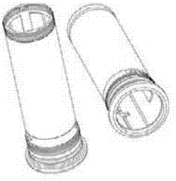
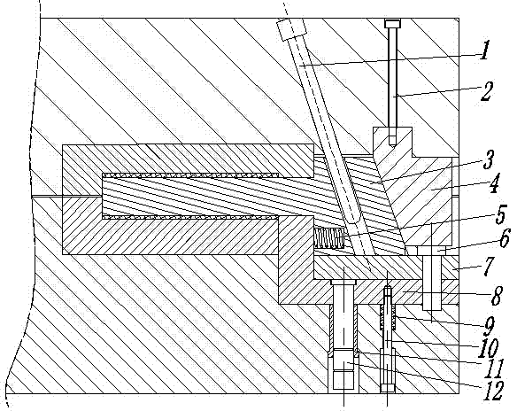
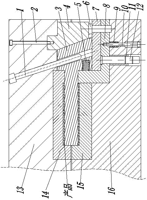
[0013] Figure 1-3 Shown is the relevant explanatory drawing of the present invention;

[0014] A floating slider core-pulling and demoulding mechanism, including an inclined guide column 1, a compression block screw 2, a long core slider body 3, a compression block 4, a slider body spring 5, and a slider body limit pin 6 , slider body chute plate 7, material retaining floating plate 8, floating plate spring 9, floating plate pull rod 10, guide sleeve 11, floating plate guide post 12, such as figure 2 shown.

[0015] The inclined guide post 1 is installed on the mold template, and the pressing block 4 is installed on the mold template through the pressing block screw 2;

[0016] The long core slider body 3 is installed on the slider body chute plate 7, and can move left and right along the inner chute of the slider body chute plate 7; the slider body limit pin 6 is installed on the slider body chute plate 7, the slider body spring 5 is compressed and installed in...


PUM


Abstract

The invention provides a floating type sliding block core pulling and demoulding mechanism. The floating type sliding block core pulling and demoulding mechanism comprises a slider angle pin, a compressing block screw, a long core sliding block body, a compressing block, a sliding block body spring, a sliding block body limiting pin, a sliding block body sliding groove plate, a blocking floating plate, a floating plate spring, a floating plate pull rod, a guide sleeve and a floating plate guide column. According to the floating type sliding block core pulling and demoulding mechanism in the technical scheme, in the mould shaping process of tubular plastic products with the small circular tube diameter and large length, mould design height can be effectively reduced, it can be guaranteed that ejection marks are not reserved on the products in the ejection process, the forming quality of the products is effectively guaranteed, and mould production and manufacturing cost and product injection molding cost are lowered. The mould structural design is reasonable, the structure is compact, work is stable, safety and reliability are achieved, and use is convenient.

Description

technical field [0001] The invention relates to the field of injection mold mechanism design, in particular to a floating slider core-pulling and demoulding mechanism. Background technique [0002] The diameter is relatively small, but the length is long, and when the tubular plastic products are molded with a length of more than 200mm, such as figure 1 As shown, if the mold layout adopts the vertical layout along the length direction, the mold height and manufacturing difficulty of the mold will be increased; if the horizontal layout is adopted, there will be obvious ejection marks on the surface, which will affect the appearance quality of the product, and it will take a long time In view of this, when the horizontal layout design is adopted, a new core-pulling and demoulding mechanism must be designed, which not only reduces the height of the mold, but also ensures the appearance quality of the product. Contents of the invention [0003] The technical problem to be sol...

Claims


Application Information

Patent Timeline
Patent Type & Authority Applications(China)
IPC IPC(8): B29C45/33B29C45/40
CPCB29C45/332B29C45/33B29C45/40B29C45/401B29C2045/4063B29L2023/00
Inventor 耿晓冬
Owner 耿晓冬
Why Eureka
Try Eureka