
Continuous countercurrent supercritical fluid extraction equipment and method applied to materials

A supercritical fluid and extraction technology, applied in chemical instruments and methods, solvent extraction, separation methods, etc., can solve the problems of high equipment cost of extraction tower, inconvenient operation and maintenance, limit of theoretical plate number, etc., to increase theoretical plate The effect of reducing the design height and avoiding errors

Inactive Publication Date: 2011-03-23
大连卓尔高科技有限公司
View PDF5 Cites 4 Cited by
  • Summary
  • Abstract
  • Description
  • Claims
  • Application Information

AI Technical Summary

Problems solved by technology

[0008] In order to solve the problems of high equipment cost and inconvenient operation and maintenance caused by the excessively high extraction tower of supercritical fluid continuous countercurrent extraction, the present invention uses the same extraction tower to conduct supercritical fluid continuous countercurrent extraction experiments or industrial production on various liquid materials. When the number of theoretical plates (that is, the height of the tower) is limited, a kind of equipment and method that can reduce the height of the tower and can extract the tower for a variety of different liquid materials is provided.

Method used

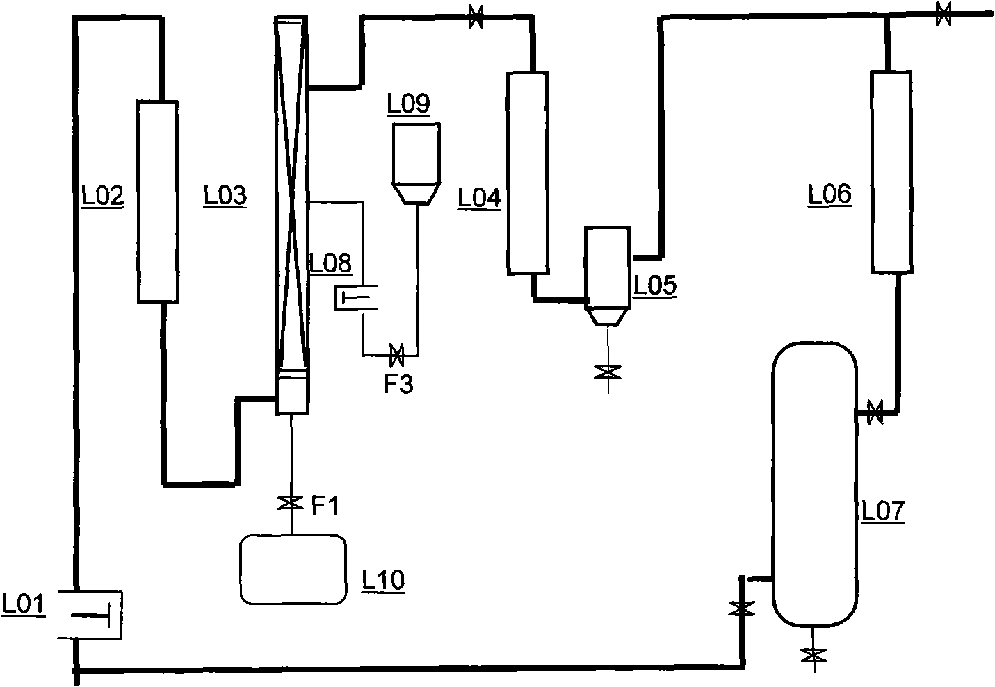
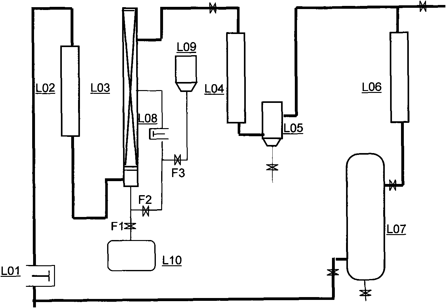
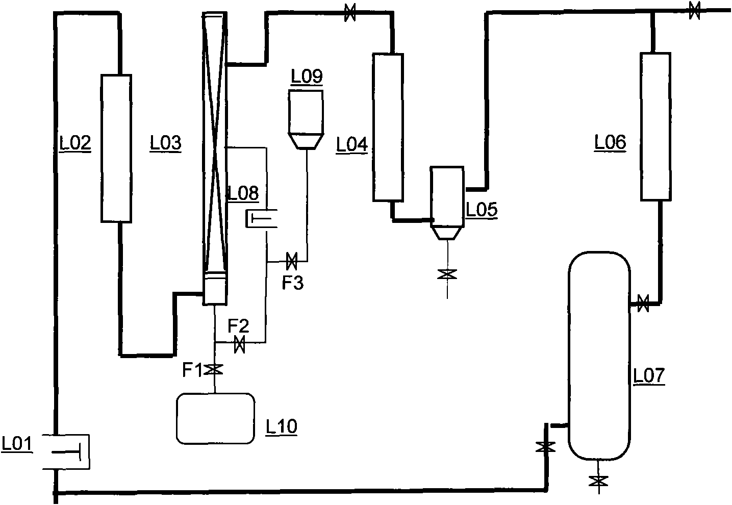

Image

  • Continuous countercurrent supercritical fluid extraction equipment and method applied to materials
  • Continuous countercurrent supercritical fluid extraction equipment and method applied to materials
  • Continuous countercurrent supercritical fluid extraction equipment and method applied to materials

Examples


Embodiment Construction

[0014] A kind of equipment and method (see attached figure 2 ), is that there is a booster pump L01, the lower part is connected with the preheater L02 and the countercurrent extraction tower L03 through the pipeline in turn, and the upper outlet of the countercurrent extraction tower L03 is connected with the heat exchanger L04 and the separation unit L05 through the pipeline, with The feed pipeline of the raw material pump L08 communicates with the upper part of the countercurrent extraction tower L03. The discharge pipeline at the bottom of the countercurrent extraction tower is divided into two circuits, one is equipped with a discharge valve F1, and the other is equipped with a raw material circulation valve F2, which is connected to the feed pipeline at the suction end of the raw material pump L08 through the pipeline. The feed pipe at the suction end of the raw material pump L08 is connected in parallel with the outlet pipeline of the raw material tank and the valve F3...


PUM


Abstract

The invention discloses continuous countercurrent supercritical fluid extraction equipment applied to a plurality of materials and a continuous countercurrent supercritical fluid extraction method applied to the plurality of materials, which aim to solve the problems of high equipment cost and inconvenience of operation and maintenance caused by the excessive height of an extraction tower. A pressurizing pump is communicated with the bottom of the extraction tower by a pipeline. A raw material pump is communicated with a feeding pipeline and a feeding valve, and is communicated with the upper part of the extraction tower by the pipeline. A material outlet at the top of the tower is communicated with a separator by the pipeline. The bottom end of the extraction tower is divided into two parallel pipelines which are provided with a discharge valve and a raw material circulating valve respectively. The pipeline with the raw material circulating valve is communicated with the intake end of the raw material pump. Materials to be extracted flow through the extraction tower from the top down, and are discharged from the bottom of the extraction tower and pumped into the extraction tower again by the raw material pump for cyclic extraction, and the extracted raw materials are discharged from a discharge pipeline at the bottom of the extraction tower. The raw materials are cyclically extracted for twice or more than twice, so the number of theoretical plates of the conventional extraction tower is multiplied, and the height of the extraction tower is greatly reduced.

Description

technical field [0001] The invention belongs to the field of extraction and separation of chemical engineering, in particular, the invention relates to a device and method for countercurrent continuous extraction of liquid raw materials using supercritical fluid as a solvent Background technique [0002] At present, the equipment and methods used for liquid raw material extraction in the field of supercritical fluid extraction in China are relatively rough: in practical applications, it is more common to use solid raw material batch extraction kettles for supercritical fluid extraction of liquid raw materials, commonly known as "solid-liquid dual-purpose ". Since the extraction kettle for extracting solid raw materials is usually designed as a "short and fat" type with a small length-to-diameter ratio, it is often easy to cause liquid flooding or uneven distribution of supercritical fluid when used to extract liquid raw materials, which affects the extraction effect; in addi...

Claims


Application Information

Patent Timeline
Patent Type & Authority Applications(China)
IPC IPC(8): B01D11/00B01D11/04
Inventor 黄宓兰赵国斌
Owner 大连卓尔高科技有限公司
Learn More