Train track occupation detection method and device based on satellite positioning

A technology of satellite positioning and detection method, which is applied in the field of train track occupancy detection based on satellite positioning, can solve the problems of high human resource cost, equipment maintenance cost and high construction cost

Active Publication Date: 2015-07-08
BEIJING JIAOTONG UNIV
View PDF5 Cites 10 Cited by
  • Summary
  • Abstract
  • Description
  • Claims
  • Application Information

AI Technical Summary

Problems solved by technology

[0007] The above-mentioned existing track occupancy detection methods are realized by using ground equipment such as track circuits or axle counters, and the construction cost is relativ...

Method used


Image

  • Train track occupation detection method and device based on satellite positioning
  • Train track occupation detection method and device based on satellite positioning
  • Train track occupation detection method and device based on satellite positioning

Examples


Embodiment 1

[0124] The embodiment of the present invention mainly aims at the operation requirements of low-density railway lines, and proposes and designs a method for judging the track occupancy of interval trains based on satellite positioning. The method involves technologies such as satellite positioning, wireless communication, track electronic map, and map matching. Track occupancy during interval operation, so as to control the tracking operation of multiple trains and ensure the safe operation of trains on the railway.

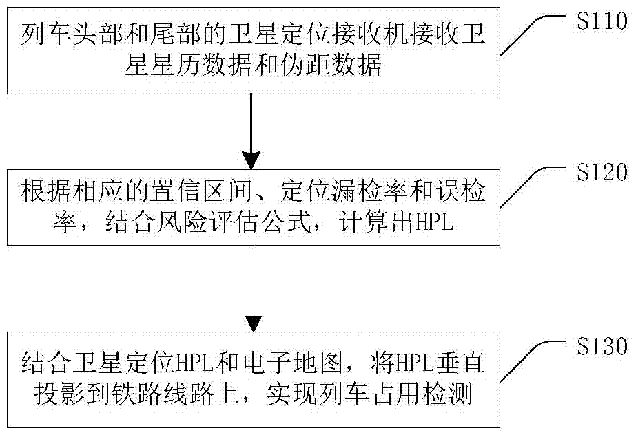
[0125] The processing flow of a satellite positioning-based train track occupancy detection method provided in this embodiment is as follows: figure 1 As shown, the following processing steps are included:

[0126] Step S110, the satellite positioning receivers at the head and tail of the train receive satellite ephemeris data and pseudorange data.

[0127] In the embodiment of the present invention, satellite positioning receivers need to be installed at the fr...

Embodiment 2

[0188] This embodiment provides a kind of train track occupancy detection device based on satellite positioning, and its concrete realization structure is as follows Figure 7 As shown, it can specifically include the following modules:

[0189] The positioning position calculation module 71 is used to receive satellite ephemeris data and pseudo-range data through the satellite positioning receivers at the head and tail of the train, and calculate the head and tail of the train according to the satellite ephemeris data and pseudo-range data positioning position;

[0190] The positioning horizontal protection distance calculation module 72 is used to calculate the positioning horizontal protection distance of the train according to the set positioning missed detection rate and false detection rate;

[0191] The occupied interval calculation module 73 is used to map the positioning positions of the front and rear of the train on the track line according to the positioning level...


PUM


Abstract

The embodiment of the invention provides a train track occupation detection method and a train track occupation detection device based on satellite positioning. The method mainly comprises the steps: satellite positioning receivers on the head and the tail of a train are used for receiving satellite ephemeris data and pseudorange data, and positioning positions of the head and the tail of the train are calculated according to the satellite ephemeris data and the pseudorange data; a positioning horizontal protection distance of the train is calculated according to a set positioning omission rate and a false detection rate; and the positioning positions of the head and the tail of the train are mapped on a track line by combining with an electronic map according to the positioning horizontal protection distance of the train, so that an occupation section of the train on the track line can be obtained. According to the embodiment of the invention, the satellite positioning receivers are arranged on the head and the tail of the train, so that the occupation calculation of the train on the section track can be completed by only utilizing vehicle-mounted apparatuses, ground apparatuses such as track circuits or axle counters are not needed, the constriction cost and the maintenance cost of the ground apparatuses are greatly saved, and the cost is greatly saved.

Description

technical field [0001] The invention relates to the technical field of train operation control, in particular to a method and device for detecting train track occupancy based on satellite positioning. Background technique [0002] When the train is running on the railway, the detection of track occupancy is the basis of the train operation control. The detection and confirmation of whether the railway line is free or occupied is an important condition to ensure the safety of railway traffic. At present, the existing orbit occupancy determination methods are as follows: [0003] (1), track circuit [0004] The components of the track circuit are: information sending equipment, rails, and information receiving equipment. Its working principle is: the information sending equipment uses two steel rails as the transmission line to transmit the information to the information receiving equipment. When the train wheel set steps on the rail, the rail is short-circuited, and the in...

Claims


Application Information

Patent Timeline
IPC IPC(8): B61L21/06
Inventor 王剑蔡伯根刘江上官伟王忠立郑波靳成铭
Owner BEIJING JIAOTONG UNIV
Why Eureka
Try Eureka