
Channel dividing conveying device for conical flask

A technology for conveying equipment and conical flasks, which can be used in conveyors, conveyor objects, packaging, etc., and can solve problems such as easy dumping

Active Publication Date: 2015-07-08
SHANGBAOTAI MACHINERY TECH KUNSHAN
View PDF7 Cites 4 Cited by
  • Summary
  • Abstract
  • Description
  • Claims
  • Application Information

AI Technical Summary

Problems solved by technology

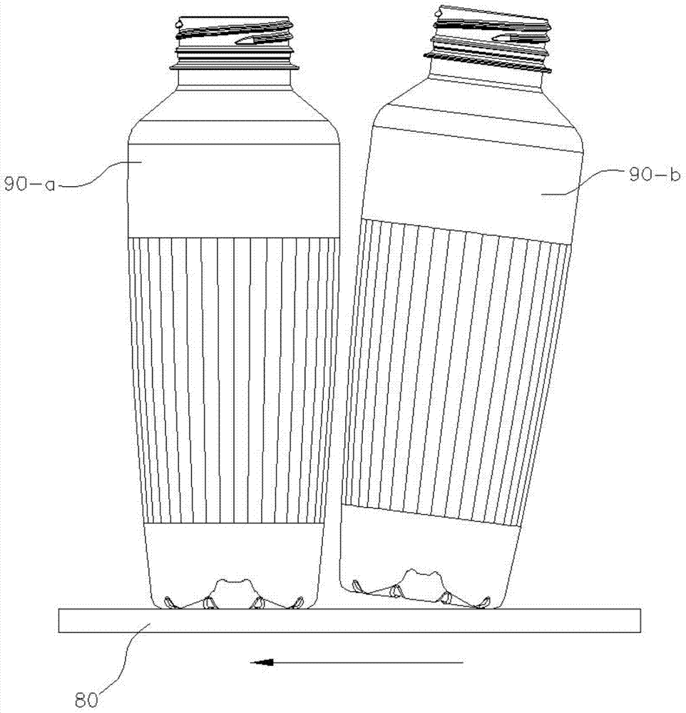
However, this kind of delivery method has the following disadvantages: figure 1 As shown, when the Erlenmeyer bottle 90-a located in the front encounters an obstacle, or slips with the conveyor belt 80, or the Erlenmeyer bottle 90-b running behind it is faster than the Erlenmeyer bottle 90-a in front of it, it is located in the rear Erlenmeyer flask 90-b for easy pouring

Method used


Image

  • Channel dividing conveying device for conical flask
  • Channel dividing conveying device for conical flask
  • Channel dividing conveying device for conical flask

Examples


Embodiment Construction

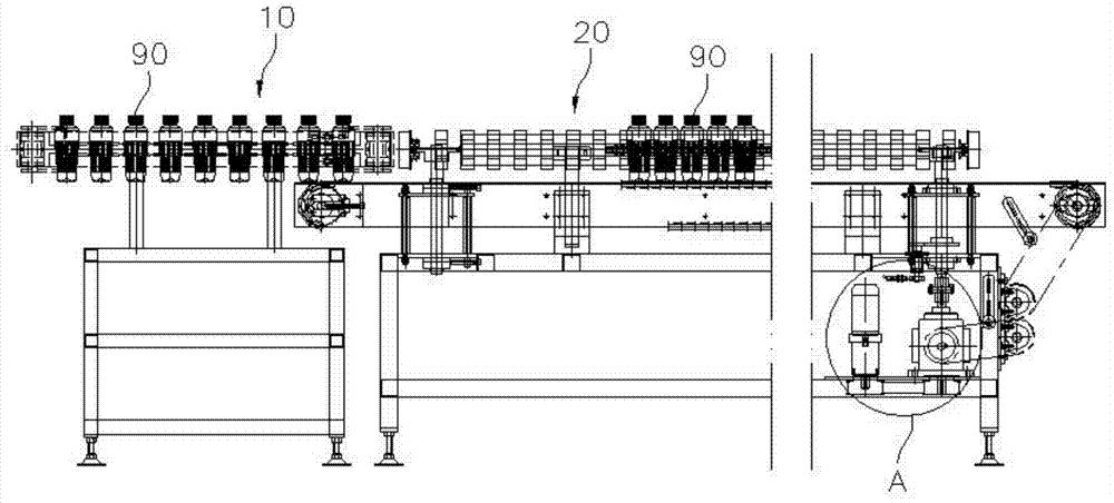
[0037] combine figure 2 , Figure 4 , Figure 5 , an Erlenmeyer flask lane-separating conveying equipment, comprising a linear conveying device 10, a lane-dividing conveying mechanism 20, and a lane-dividing device 30.

[0038] combine Image 6 , Figure 7 , the linear conveying device 10 includes a linear conveying unit 11, a horizontal conveying base plate 12, the linear conveying unit 11 includes a conveyor belt 111, a pair of rollers 112 for driving the conveyor belt, and a motor 113 for driving the rollers 112 to rotate, The pair of rollers 112 are vertically pivoted on the horizontal conveying bottom plate 12, the number of the linear conveying units 11 is two, and the two linear conveying units 11 are arranged side by side on the horizontal conveying bottom plate 12, the two The gap between the linear conveying units 11 is equal to the maximum outer diameter of the Erlenmeyer flask 90 .

[0039] Such as Figure 4 As shown, the lane-dividing conveying mechanism 20...


PUM


Abstract

The invention discloses a channel dividing conveying device for a conical flask. The device comprises a linear conveying device, a channel dividing conveying mechanism and a channel dividing device, wherein the linear conveying device comprises a pair of linear conveying units and a horizontal conveying bottom plate; the channel dividing conveying mechanism comprises two channel dividing conveying devices, and each channel dividing conveying device is joined with the linear conveying device; the channel dividing device is positioned at the part in which the channel dividing conveying mechanism is connected with the linear conveying device, comprising an oscillating block; the conical flask is clamped to move forwards through a pair of linear conveying units of the linear conveying device, and therefore, the conical flask can be avoided inclining during operation; when, the quantity of the conical flasks moving into each channel dividing conveying device is controlled though the channel dividing device as the oscillating block oscillates; each channel dividing conveying device quantitatively conveys the conical flasks to a packing machine for mass packing.

Description

technical field [0001] The invention relates to the technical field of beverage bottle conveying, in particular to a conical bottle lane-dividing conveying device. Background technique [0002] Such as figure 1 Shown, a kind of Erlenmeyer flask 90, according to the prior art, the conveyer belt 80 that conveys described Erlenmeyer flask 90 is generally arranged horizontally in the production process, that is, the conveyer belt 80 is passed through its contact friction with the Erlenmeyer flask 90 bottom surface. The force drives the Erlenmeyer flask to displace by 90°. However, this kind of delivery method has the following disadvantages: figure 1 As shown, when the Erlenmeyer bottle 90-a at the front encounters an obstacle, or slips with the conveyor belt 80, or the Erlenmeyer bottle 90-b behind it runs at a speed greater than that of the Erlenmeyer bottle 90-a ahead of it, it is located at the rear The Erlenmeyer 90-b is easy to pour. Contents of the invention [0003...

Claims


Application Information

Patent Timeline
IPC IPC(8): B65G47/64
CPCB65G47/648B65G2201/0244B65G2207/28
Inventor 吴海奇
Owner SHANGBAOTAI MACHINERY TECH KUNSHAN
Learn More