Evaporator source, evaporation device and evaporation method

An evaporation source and evaporation technology, which is applied in the field of evaporation devices and evaporation sources, can solve the problems of reduction and waste of organic evaporation materials, yield and device performance, and achieve the effects of avoiding waste and good thickness uniformity.

Inactive Publication Date: 2015-07-08
BOE TECH GRP CO LTD +1
View PDF0 Cites 16 Cited by
  • Summary
  • Abstract
  • Description
  • Claims
  • Application Information

AI Technical Summary

Problems solved by technology

[0005] The present invention aims at the problems of stoppage of all organic evaporation chambers caused by nozzle clogging of existing evaporation sources, serious waste of organic evaporation materials, and reduction of output and device performance, and provides a method that can individually solve nozzle clogging to increase output and Evaporation sources for device performance

Method used


Image

  • Evaporator source, evaporation device and evaporation method
  • Evaporator source, evaporation device and evaporation method
  • Evaporator source, evaporation device and evaporation method

Examples


Embodiment 1

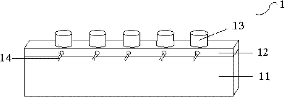
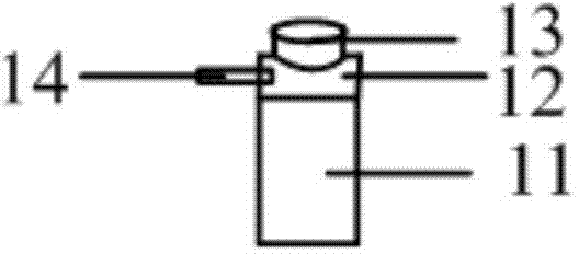
[0030] Such as figure 2 As shown, the present embodiment provides an evaporation source 1, which includes a crucible 11 for generating evaporation gas; a crucible nozzle 13 for ejecting the evaporation gas from the crucible 11; and a plugging heater 14 for The crucible nozzle 13 is heat-treated.

[0031] Preferably, the evaporation source 1 further includes a crucible top cover 12 , the crucible top cover 12 covers the crucible 11 , the crucible nozzle 13 is arranged on the crucible top cover 12 , and the plugging heater 14 is arranged in the crucible top cover 12 .

[0032] That is to say, a crucible top cover 12 can be covered on the crucible 11 that holds and heats the organic evaporation material, and the crucible top cover 12 is provided with a crucible nozzle 13. At this time, the plugging heater 14 can be buried in the crucible top cover The inside of 12 corresponds to the position of the crucible nozzle 13 .

[0033] Wherein, preferably, each crucible nozzle 13 corr...

Embodiment 2

[0038] Such as Figure 4 to Figure 6 As shown, the present embodiment provides a kind of evaporation source, and it has the structure similar to the evaporation source of embodiment 1, and its difference with embodiment 1 is that the plugging heater 14 is arranged on the crucible top cover 12 around the crucible nozzle 13 Location.

[0039] That is to say, the plugging heater 14 is arranged on the surface of the crucible top cover 12 , and the crucible nozzle 13 is enclosed in the plugging heater 14 .

[0040] Preferably, the blockage heater 14 is a ring heater, and the ring heater is composed of a plurality of heating plates arranged on the crucible top cover 12 for heating the crucible nozzle 13, and the heating plates Openings corresponding to the positions of the multiple crucible nozzles 13 are provided for covering the multiple crucible nozzles 13 .

[0041] Such as Figure 4 , Figure 5As shown, the circle heater takes a rectangular circle heater as an example, the ...

Embodiment 3

[0045] Such as Figure 7 As shown, the present embodiment provides an evaporation source, which has a structure similar to that of the evaporation sources of Embodiments 1 and 2, and its difference from Embodiments 1 and 2 is that the evaporation source 1 also includes a driving device 16, which blocks the heater 14 is arranged on the driving device 16, and the driving device 16 is used to drive the blocking heater 14 to move.

[0046] Such as Figure 7 As shown, the driving device 16 is arranged above the crucible 11 , the plugging heater 14 is arranged on the driving device 16 , and the driving device 16 can drive the blocking heater 14 to move. When the organic vapor deposition material to be evaporated was solidified in the crucible nozzle 13, the driving device 16 would drive the blocked heater 14 to move to the blocked crucible nozzle 13, and when arriving above the blocked crucible nozzle 13, the blocked heater 14 would directly The crucible nozzle 13 is heated to eva...


PUM


Abstract

The invention provides an evaporator source, an evaporation device and an evaporation method, and belongs to the technical field of evaporation equipment. The problems that by means of an existing evaporator source, all organic evaporation chambers are stopped being used due to the fact that a nozzle is blocked, organic evaporating materials are wasted seriously, and the yield and the device performance are lowered can be solved. The evaporator source comprises a crucible used for generating evaporating gas and a crucible nozzle used for making the evaporating gas spray out of the crucible, and the evaporator source further comprises a blocking heater used for heating the crucible nozzle.

Description

technical field [0001] The invention belongs to the technical field of evaporation equipment, and in particular relates to an evaporation source, an evaporation device and an evaporation method. Background technique [0002] Organic Light-Emitting Diode (OLED) has self-illumination, no need for backlight, high contrast, thin thickness, wide viewing angle, fast response, can be used for flexible panels, wide operating temperature range, structure and The production process is relatively simple and other excellent characteristics, and it is considered to be the new application technology of the next generation flat panel display. [0003] At present, evaporation equipment is mainly used to prepare OLEDs. Usually, the evaporation equipment is equipped with multiple organic evaporation chambers, and each organic evaporation chamber is equipped with an evaporation source. The evaporation source includes a crucible and a crucible nozzle. The organic evaporation The plating materi...

Claims


Application Information

Patent Timeline
Patent Type & Authority Applications(China)
IPC IPC(8): C23C14/24C23C14/12
CPCC23C14/24C23C14/243C23C14/564C23C14/12
Inventor 胡海兵
Owner BOE TECH GRP CO LTD
Why Eureka
Try Eureka