Stripping device for electro-deposited metal

A pre-stripping and electrodeposition technology, applied in the electrolysis process, electrolytic components, etc., can solve problems such as not easy to be stripped, tearing in the middle of the upper part of the zinc sheet, scratches on the cathode plate and the zinc sheet, etc., and achieve the success rate of pre-stripping Convenience, high pre-stripping success rate, and strong zinc stripping ability

Active Publication Date: 2015-07-08
BEIJING GENERAL RES INST OF MINING & METALLURGY +1
View PDF10 Cites 11 Cited by
  • Summary
  • Abstract
  • Description
  • Claims
  • Application Information

AI Technical Summary

Problems solved by technology

Manufacturers who have used these equipment have found such a problem: because the bonding force between the electrolytic metal and the cathode plate is very tight, it is not easy to be peeled off, especially the bonding force between the upper edge of the metal and the cathode plate is relatively large.
There is a very serious problem with this technology: the noise hazard
The problem found in the practical application is that the pre-stripping cannot be successfully achieved only by the small chisels on both sides. Due to the poor zinc electrolysis process in China, the phenomenon of tearing in the middle of the upper part of the zinc sheet often occurs
[0014] This pre-stripping method is easy to damage the tool due to the instantaneous dynamic impact, and the pre-stripping tool needs to be replaced frequently. In addition, it has high requirements for the equipment itself, and the blade must be absolutely parallel to the cathode plate surface, otherwise the impact will damage the cathode plate and zinc. Severe scratches caused by

Method used


Image

  • Stripping device for electro-deposited metal
  • Stripping device for electro-deposited metal
  • Stripping device for electro-deposited metal

Examples


specific Embodiment

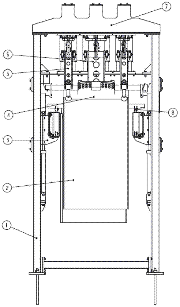
[0068] figure 1 A pre-stripping device 7 for stripping the electrodeposited metal 2 from the cathode plate 4 is shown.

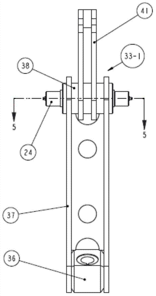
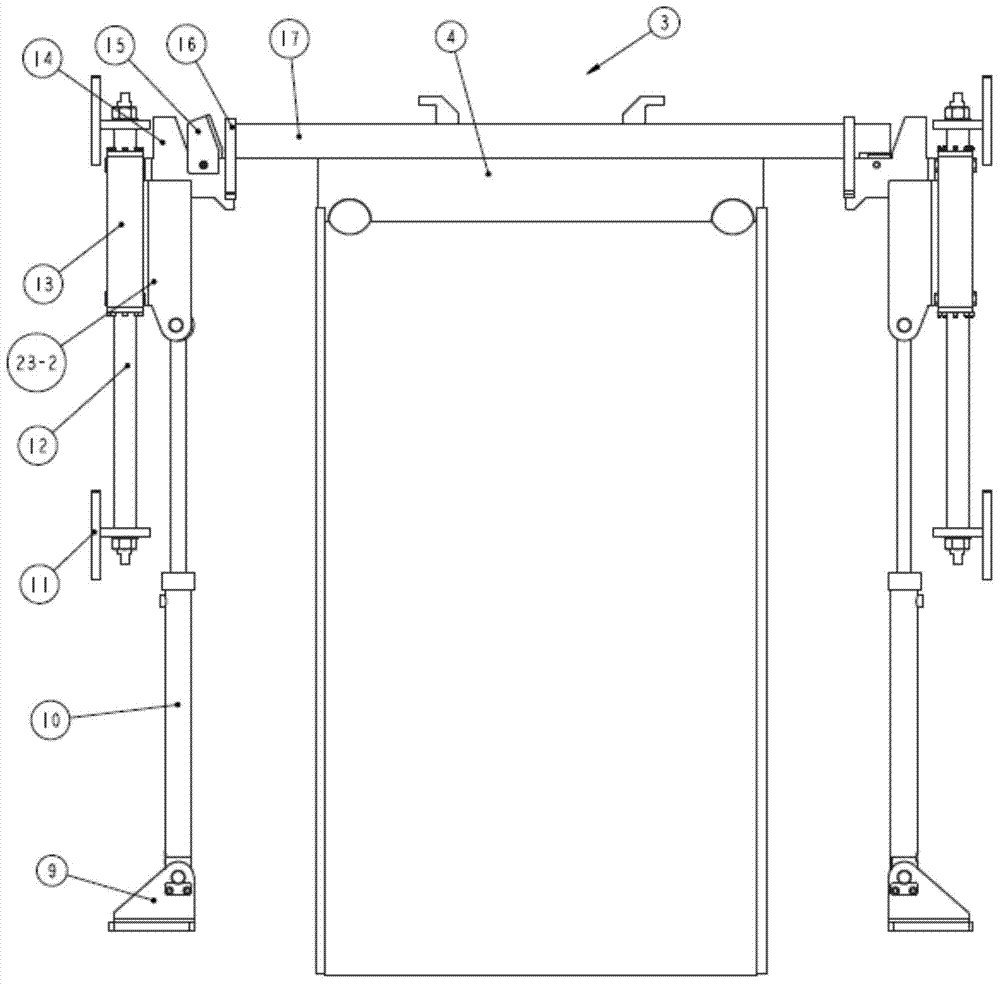
[0069] The pre-stripping device 7 includes: a frame 1, a lifting device 3, a knife assembly 5 and an oblique stripping knife assembly 6. The lifting device 3 lifts the cathode plate 4 on the conveyor chain 8 to the station to be stripped, and the opening and closing oil cylinder 31 of the knife assembly 5 drives its first rear driving arm 20-1 and the first front driving arm 33-1 to close, by Depress the oil cylinder 28 to drive the knife assembly 5 to go down, and stop moving when the knife assembly 5 descends about 100mm, and the opening and closing oil cylinder 31 of the oblique stripping knife assembly 6 drives its second front drive arm 33-2 and the second rear drive arm 20-2 Closed, the oblique stripping knife assembly 6 is driven downward by pressing down the oil cylinder 28, and stops when the oblique stripping knife assembly moves down about 60mm, ...


PUM


Abstract

The invention discloses a stripping device for electro-deposited metal. The device comprises a rack, knife assemblies on the two sides, a middle inclined stripping knife assembly and a lifting device, wherein the rack comprises a base, a stand column, an L-shaped support, a beam and an upper rack body, the knife assemblies on the two side comprise two sets of knife assemblies distributed on the left side and the right side of a cathode plate, and each knife assembly comprises a pre-stripping knife, a first front driving arm, a first back driving arm, a first guiding device, a synchronization mechanism, an opening and closing oil cylinder and a downward-pressing oil cylinder; the middle inclined knife assembly comprises an inclined stripping knife, a second front driving arm, a second rear driving device, a first guiding device, a synchronization mechanism, an opening and closing oil cylinder and a downward-pressing oil cylinder; the lifting device comprises a lifting oil cylinder, a second guiding device, a cathode plate hook and a cathode conductive head adjusting block. The stripping device is small in size, high in zinc stripping capacity, high in pre-stripping success rate and high in applicability and efficiency and sub-sequent zinc stripping operation is facilitated.

Description

technical field [0001] The invention relates to an auxiliary equipment for hydrometallurgy, in particular to an electrodeposited metal pre-stripping device. Background technique [0002] The process of hydrometallurgy is to absorb the metal produced by electrolysis on the cathode plate, then peel off the metal layer from the cathode plate, and melt and cast it into an ingot. Stripping the electrolytically produced metal layer from the cathode plate is a non-trivial process that can be done manually or mechanically. However, as the area of ​​the cathode plate becomes larger and larger, the method of manual stripping becomes more and more unrealistic, which not only consumes huge manpower, but also is not conducive to the improvement of productivity. In order to save labor and increase productivity, in the 1970s, some foreign manufacturers began to develop mechanical equipment to strip these metals, and achieved remarkable results. Manufacturers who have used these devices h...

Claims


Application Information

Patent Timeline
Patent Type & Authority Applications(China)
IPC IPC(8): C25C7/08
Inventor 赵继平郭鑫姜勇李恒通段辰玥龙智卓战凯石峰顾洪枢冯孝华李建国杨文旺吴涛
Owner BEIJING GENERAL RES INST OF MINING & METALLURGY
Why Eureka
Try Eureka