Heat exchanger fin and heat exchanger
A technology of heat exchangers and fins, applied in heat exchange equipment, lighting and heating equipment, tubular elements, etc., can solve the problems of reduced comprehensive performance of fins, smaller flow area, increased wind resistance, etc., to reduce fins Effects of air resistance, improvement of overall performance, and balance of heat transfer performance
- Summary
- Abstract
- Description
- Claims
- Application Information
AI Technical Summary
Problems solved by technology
Method used
Image

Examples
Embodiment 1
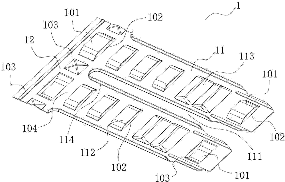
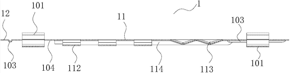
[0029] This preferred embodiment provides a heat exchanger fin. Such as figure 1 with figure 2 As shown, the fin 1 includes a connected fin body 11 and a fin edge 12, the fin body 11 is provided with a flat tube groove 111 for passing through the flat tube 2, and the fin body 11 and / or the fin edge A support 101 is protrudingly provided on the surface of 12 . The support member 101 is in the shape of an arch bridge, and opening structures are provided on both sides of the support member 101 , and the opening structures form the wind passage 102 along the surface of the fin 1 .
[0030] The wind passing channel 102 formed between the support member 101 and the surface of the fin 1 is beneficial to reduce the wind resistance of the fin, the comprehensive performance of the fin 1 is further improved, and the noise generated when the wind flows through the fin 1 is reduced.
[0031] A plurality of arched fin bridges 112 are arranged on the fin body 11 . Opening structures are...
Embodiment 2
[0037] This preferred embodiment provides a heat exchanger fin whose structure is basically the same as that of the first preferred embodiment. The fin includes a connected fin body and a fin edge, the fin body is provided with a flat tube groove for passing through a flat tube, and a support member is protrudingly provided on the surface of the fin body and / or the fin edge , the supporting member is in the shape of an arch bridge, and opening structures are arranged on both sides of the supporting member, and the opening structures form air passages along the surface of the fins.
[0038] The difference is that no other structures (fin bridges, corrugated protrusions, ribs, etc.) Fin wind resistance.
Embodiment 3
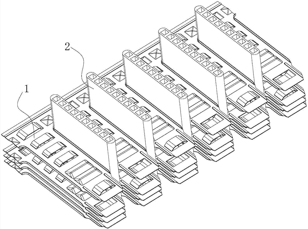
[0040] This preferred embodiment provides a heat exchanger. Such as image 3 with Figure 4 As shown, the heat exchanger includes a plurality of flat tubes 2 and a plurality of fins 1 as described in the preferred embodiment 1 or 2, and the flat tubes 2 are snapped into the flat tube grooves 111 .
[0041] The support separates two adjacent fins at a certain distance to ensure sufficient air flow through the fins to avoid serious attenuation of the performance of the whole machine due to condensation and frost.
[0042] Each fin 1 is sequentially stacked forward to form a fin group, and a plurality of flat tubes 2 are respectively snapped into the flat tube grooves 111 of the fin group, and the distance between the fins is equal to the height of the support; or, the plurality of fins 1. The fin group is formed by stacking forward and reverse in sequence, and a plurality of flat tubes 2 are respectively snapped into the flat tube grooves 111 of the fin group. The bridge heig...
PUM
 Abstract
Description
Claims
Application Information
 - Generate Ideas
- Intellectual Property
- Life Sciences
- Materials
- Tech Scout
- Unparalleled Data Quality
- Higher Quality Content
- 60% Fewer Hallucinations
Browse by: Latest US Patents, China's latest patents, Technical Efficacy Thesaurus, Application Domain, Technology Topic, Popular Technical Reports.
© 2025 PatSnap. All rights reserved.Legal|Privacy policy|Modern Slavery Act Transparency Statement|Sitemap|About US| Contact US: help@patsnap.com