
Non-contact automatic gas sample retention device

A non-contact, fully automatic technology, applied in the direction of sampling devices, etc., can solve the problems of heating gas or air bag safety accidents, inaccurate verification and analysis results, and large labor costs, so as to save labor costs and improve production safety sex, the effect of eliminating mistakes

Active Publication Date: 2017-10-03
苏州聚阳环保科技股份有限公司
View PDF9 Cites 0 Cited by
  • Summary
  • Abstract
  • Description
  • Claims
  • Application Information

AI Technical Summary

Problems solved by technology

[0003]Current conventional methods rely on manual sample retention, which not only takes time and effort, but also makes the company bear a lot of labor costs. Control when the sample should be retained, and how much to retain, it is very likely that the most representative sample gas will be missed or the amount of gas required for the verification will not be retained, which will bring inconvenience to future research and verification
Moreover, in the existing artificial gas sample retention process, because workers directly contact the air bag, improper operation can easily cause pollution and loss of the retained sample gas, resulting in inaccurate subsequent verification and analysis results, failing to achieve the desired purpose
[0004]Another important point is that for a type of gas that is easy to adsorb and stick, it needs to be heated throughout the process of transportation and sample retention, so it is required to prepare special heating equipment , the processing is more troublesome, which not only greatly increases the burden on workers, but also increases the production cost of enterprises
Moreover, workers accidentally contacting heating gas or air bags during the sample retention process may easily cause unnecessary safety accidents

Method used


Image

  • Non-contact automatic gas sample retention device

Examples


Embodiment

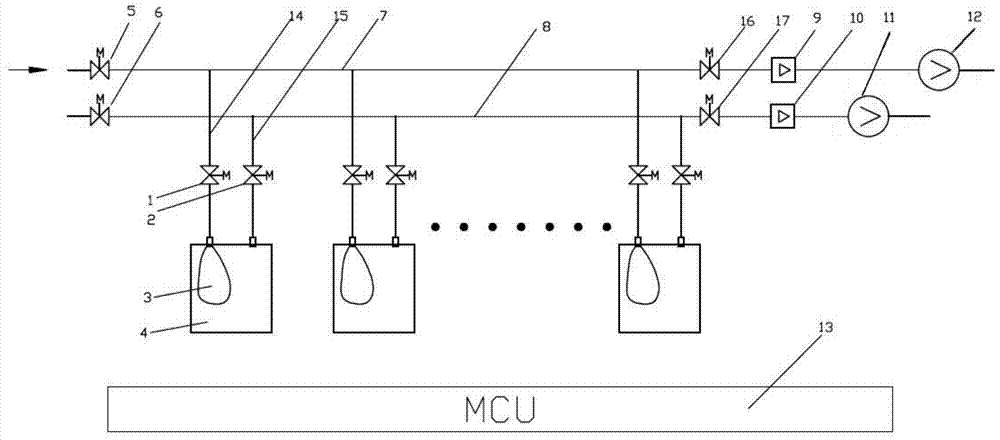
[0035] Example: Combine figure 1 Shown is a specific embodiment of the non-contact fully automatic gas sample retention device of the present invention, which has sampling pipes 7 and air pipelines 8 arranged in parallel, wherein:

[0036]The sampling pipe 7 is provided with a sample gas valve 5, an evacuation flowmeter 9 and an air pump 12 in sequence, and the sampling pipe 7 between the sample gas valve 5 and the evacuation flowmeter 9 is provided with an air bag connection area, which A plurality of gas bags 3 are connected through the sample gas branch pipe 14, and each sample gas branch pipe 14 is provided with a communication valve 1. And described air pipeline 8 is provided with air valve 6, sampling flowmeter 10 and sampling air pump 11 successively, and is provided with vacuum box connection area on air pipeline 8 between air valve 6 and sampling flowmeter 10, its There are several vacuum boxes 4 corresponding to the aforementioned airbags 3 one by one connected thro...


PUM


Abstract

The invention discloses a non-contact full-automatic gas sample retention device, which comprises a sampling tube provided with a sample gas valve, an evacuation flowmeter and an air pump in sequence, and the sampling tube between the sample gas valve and the evacuation flowmeter passes through the sample The gas branch pipe is connected with several air bags, and each sample gas branch pipe is equipped with a connecting valve; it also includes an air pipeline with an air valve, a sampling flowmeter and a sampling air pump in sequence, and the connection between the air valve and the sampling flowmeter The air pipeline is connected with a number of vacuum boxes corresponding to the air bags one by one through the evacuation branch pipe. Each air bag is sealed in the corresponding vacuum box, and each evacuation branch pipe is equipped with an exhaust valve; Controller for electrical connection of flow meters, valves and air pumps. This device can not only realize the automatic and accurate sample retention of gas, improve production efficiency and save labor costs, but also the non-contact air bag design isolates manual contact, which is convenient for adding a gas heating device while improving production safety and ensuring that the gas is fully processed No pollution, no loss.

Description

technical field [0001] The invention relates to a non-contact automatic gas sample retention device. Background technique [0002] Gas sample retention is an important link in the process of gas production and detection. For gases that do not meet the standards (such as the polytetrafluoroethylene gas currently produced by the company, it has chemical stability, non-stickiness, lubricity, electrical insulation, and aging resistance. And many advantages of radiation resistance, usually used as lining materials, which need to be tested before leaving the factory), must be extracted and stored in one or more air bags for subsequent verification, analysis and verification. [0003] The current conventional practice relies on manual sample retention, which not only takes time and effort, but also makes the company bear a lot of labor costs. For gas samples that exceed the standard, it is difficult for workers to control when to retain samples and how much to retain. It is very l...

Claims


Application Information

Patent Timeline
Patent Type & Authority Patents(China)
IPC IPC(8): G01N1/24
Inventor 李伟刘超杰
Owner 苏州聚阳环保科技股份有限公司
Learn More