
A bearing pad type conductive clutch

A technology for clutches and bushings, which is applied in the field of bushing-type conductive clutches, can solve the problems of high manufacturing costs of conductive clutches, affecting the smooth operation of equipment, and hot conductive clutch plates, etc., and achieves the advantages of increased working thickness, reduced manufacturing costs, and extended service life Effect

Inactive Publication Date: 2017-01-11
XUZHOU UNIV OF TECH +1
View PDF5 Cites 0 Cited by
  • Summary
  • Abstract
  • Description
  • Claims
  • Application Information

AI Technical Summary

Problems solved by technology

[0003] In order to solve the defects of high manufacturing cost of the conductive clutch, hot conductive clutch plate during the production process, severe ablation, short service life and rapid decline in conductivity in the later period, which affects the smooth operation of the equipment, the invention provides a bearing pad type conductive clutch, which is very good Solve the above-mentioned problems of conductive clutch

Method used


Image

  • A bearing pad type conductive clutch
  • A bearing pad type conductive clutch
  • A bearing pad type conductive clutch

Examples


Embodiment 1

[0024] The bush type conductive clutch device provided by the present invention will be further described below in conjunction with the accompanying drawings.

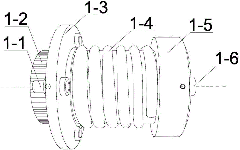
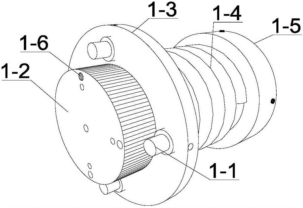
[0025] Such as figure 1 As shown, it is a schematic diagram of a sub-conductive clutch, figure 2 It is a schematic diagram of the isometric structure of the sub-conductive clutch body. It can be seen that the sub-conductive clutch body includes a fixed bolt 1-1, a push-type conductive clutch plate protrusion 1-2, a sub-conductive clutch body flange 1-3, and a return spring 1-4, spring base 1-5 and cable 1-6; among them, the push-type conductive clutch boss 1-2, the sub-conductive clutch flange 1-3, the return spring 1-4, and the spring base 1-5 Coaxial setting, the sub-conductive clutch flange 1-3 and the spring base 1-5 are respectively arranged at both ends of the sub-conductive clutch, and the return spring 1-4 is arranged on the sub-conductive clutch flange 1-3 and the spring Between the base 1-5, the push-type ...


PUM


Abstract

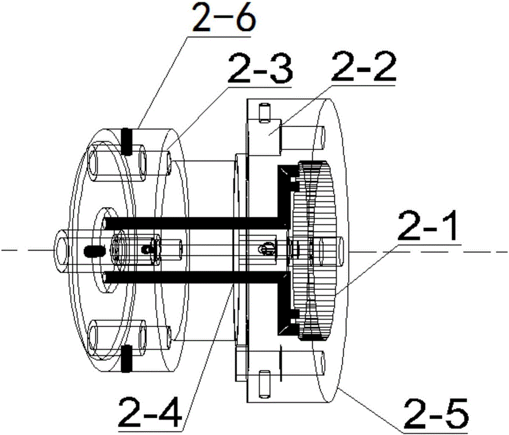
The invention discloses a bearing bush type conductive clutch. The bearing bush type conductive clutch is composed of a sub conductive clutch body and a main conductive clutch body, wherein the sub conductive clutch body comprises fixing bolts, a push-type conductive clutch disc convex column, a sub conductive clutch body flange plate, a reset spring, a spring base and cables; the main conductive clutch body comprises a sucked type conductive contact surface groove, fixing bolt grooves, a base push-type conductive clutch disc convex column mounting hole, electrical wires, a main conductive clutch body flange plate and a base. By means of the effective connection arrangement of all the parts of the sub conductive clutch body and the main conductive clutch body, the problems that the manufacturing cost of the conductive clutch is high, a conductive clutch disc is very hot and is severely burnt in the production process, the service life is short, the later period conductivity declines rapidly, and the smooth running of equipment is affected are solved, the usage range is further widened, and the service life is prolonged.

Description

technical field [0001] The invention relates to high-voltage transmission transformers, battery forklifts, cranes, electric shovels and other equipment in the field of industrial production, in particular to a bearing pad type conductive clutch, which belongs to the field of industrial manufacturing. Background technique [0002] At present, in the production and manufacture of automobiles, high-voltage transmission transformers, battery forklifts, cranes, electric shovels and other equipment, the current of the bearing pad type conductive clutch used is transmitted from the internal wire to the sub-conductive clutch plate, and the sub-conductive clutch is transferred through mechanical transmission. The female conductive clutch plate pulls in to realize the circuit connection and torque transmission of the entire equipment. The conductive clutch is the key component of current conduction and the weakest link in the conductive path. The performance of the conductive clutch di...

Claims


Application Information

Patent Timeline
Patent Type & Authority Patents(China)
IPC IPC(8): H01R24/00H01R13/08H01R13/10H01R13/502
CPCH01R13/08H01R13/10H01R13/502H01R24/00
Inventor 梁峙梁骁马捷
Owner XUZHOU UNIV OF TECH
Learn More