Current differential protecting method of wind electricity direct current microgrid under direct current bipolar short circuit failure

A current differential and bipolar short-circuit technology, applied in emergency protection circuit devices, electrical components, etc., can solve the problem of large diode impact, and achieve the effect of ensuring safe operation, avoiding system collapse, and fast protection action.

Inactive Publication Date: 2015-07-08
NORTH CHINA ELECTRIC POWER UNIV (BAODING)
View PDF2 Cites 15 Cited by
  • Summary
  • Abstract
  • Description
  • Claims
  • Application Information

AI Technical Summary

Problems solved by technology

[0037] From the above analysis, it can be seen that when a bipolar short circuit occurs in the DC line, the overcurrent protection of the converter will block the pulse, and the DC side capacitance a

Method used


Image

  • Current differential protecting method of wind electricity direct current microgrid under direct current bipolar short circuit failure
  • Current differential protecting method of wind electricity direct current microgrid under direct current bipolar short circuit failure
  • Current differential protecting method of wind electricity direct current microgrid under direct current bipolar short circuit failure

Examples


Example Embodiment

[0062] Example 1:

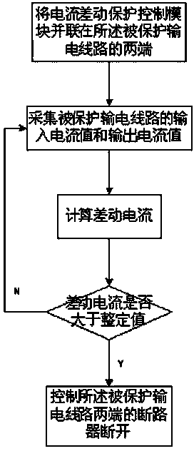
[0063] Such as figure 1 As shown, a current differential protection method for a wind power DC microgrid under a DC bipolar short circuit fault includes the following steps:

[0064] a: Connect the current differential protection control module in parallel to both ends of the protected transmission line;

[0065] b: The current differential protection control module collects the input current value of the protected transmission line i in And the output current value i out ;

[0066] c: The current differential protection control module calculates the differential current i diff :

[0067] i diff =|i L_in -i L_out | (1)

[0068] d: The current differential protection control module judges the differential current i diff Is it greater than the setting value i set , If not, go to step b, if yes, go to step e;

[0069] e: The current differential protection control module controls the circuit breakers at both ends of the protected transmission line to open.

[007...

Example Embodiment

[0071] Example 2:

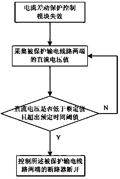
[0072] The current differential protection method of the wind power DC microgrid under the DC bipolar short circuit fault further includes an undervoltage protection step:

[0073] When the current differential protection control module fails, it is determined whether the DC voltage at both ends of the protected transmission line is lower than the set value and exceeds the predetermined time threshold; if so, the current differential protection control module controls the protected transmission line The circuit breakers at both ends are disconnected; if not, continue monitoring.

Example Embodiment

[0074] Example 3:

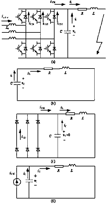
[0075] The current differential protection control module of this embodiment includes an absorption circuit, which controls the absorption circuit to close while controlling the opening of the circuit breakers at both ends of the protected transmission line. The circuit schematic diagram of the absorption loop is as follows Image 6 Shown.


PUM


Abstract

The invention discloses a current differential protecting method of a wind electricity direct current microgrid under direct current bipolar short circuit failure. When a differential current is larger than a set value, it is judged that the failure occurs, breakers at the two ends of an electric transmission line under protection are controlled to be switched off, and meanwhile an absorption circuit is switched on. By means of the method, the faulty line can be switched off rapidly in a millisecond, and a fault current is prevented from reaching an overcurrent value on account of low impedance of a system at a fast speed, so that the whole system is prevented from breakdown. When the current differential protection loses efficacy, under voltage protection serves as a second defensive line, the circuit and power electronic components such as a diode are prevented from being damaged by a large short circuit current, and the safe operation of the system is guaranteed.

Description

technical field [0001] The invention relates to a current differential protection method for a wind power DC microgrid, in particular to a current differential protection method for a wind power DC microgrid under a DC bipolar short-circuit fault. Background technique [0002] Generally speaking, short-circuit faults between poles are usually caused by external mechanical stress and are regarded as permanent faults, which need to be removed quickly and accurately, otherwise the entire DC microgrid will be paralyzed. Therefore, it is necessary to study a fast fault location and isolation scheme to ensure that the DC microgrid system can still operate safely and stably after the fault occurs on the DC line and the fault is removed. At present, research on DC microgrid protection is still in its infancy. [0003] When a bipolar short-circuit fault occurs in the DC microgrid, due to the short-circuit of the DC positive and negative poles, the DC side capacitor discharges rapidl...

Claims


Application Information

Patent Timeline
IPC IPC(8): H02H7/26
Inventor 张祥宇张丽荣王毅
Owner NORTH CHINA ELECTRIC POWER UNIV (BAODING)
Why Eureka
Try Eureka