Cooling fan and cooling device for electronic equipment and electronic equipment

A technology for electronic equipment and heat dissipation fans, applied in the fields of electrical digital data processing, instruments, calculations, etc., can solve problems such as damage, heat pipe deformation or destruction, and unstable operation, so as to ensure operational stability, set up a simple structure, and avoid system crash effect

Pending Publication Date: 2019-10-29
GUANGDONG HONGQIN COMM TECH CO LTD
View PDF0 Cites 2 Cited by
  • Summary
  • Abstract
  • Description
  • Claims
  • Application Information

AI Technical Summary

Problems solved by technology

The wall thickness of the heat pipe of a notebook computer is very thin, generally only 0.20mm or 0.25mm; the outer wall of the heat pipe is made of ordinary copper, the inside of the heat pipe is copper powder and a small amount of distilled water, and the rest is vacuum, and the heat pipe can be easily bent or shear damage
Based on the above two factors, the heat pipe of the cooling module inside the notebook is easily deformed or damaged by external force, and since the heat pipe is close to the bottom case of the system, it is very easy to cause the heat pipe to be stressed and be damaged when the bottom case of the system is hit. deformed or damaged
Once the heat pipe loses its heat conduction performance, the entire heat dissipation module will almost lose its heat dissipation capability, which will be fatal to the heat dissipation capability of the entire system, and the laptop system will crash and cannot operate stably

Method used


Image

  • Cooling fan and cooling device for electronic equipment and electronic equipment
  • Cooling fan and cooling device for electronic equipment and electronic equipment
  • Cooling fan and cooling device for electronic equipment and electronic equipment

Examples


Embodiment Construction

[0021] In order to describe the technical content and structural features of the present invention in detail, further description will be given below in conjunction with the implementation and accompanying drawings.

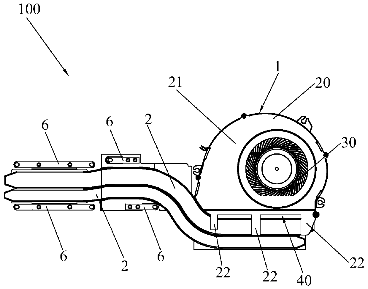
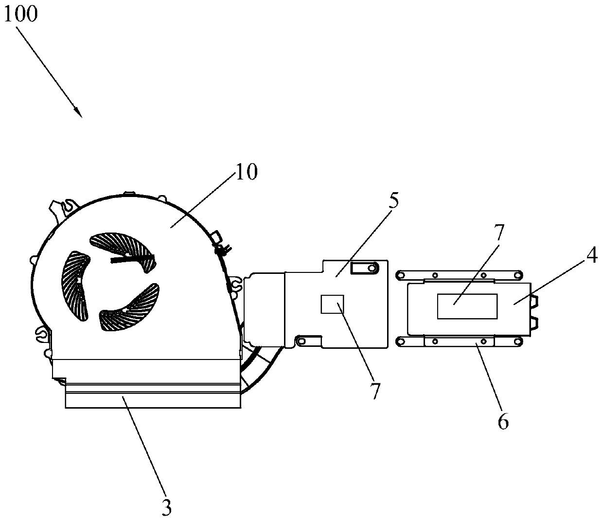
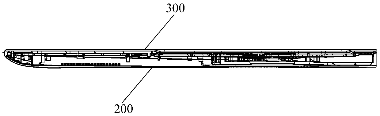
[0022] see Figure 1 to Figure 4 , the invention discloses a cooling fan 1 for electronic equipment, comprising a fan base 10, a fan cover 20 and a fan impeller 30, an air outlet 40 is formed between the fan base 10 and the fan cover 20, and the fan cover The body 20 includes a cover part 21 and an extension part 22 connected to an end of the cover part 21 close to the air outlet 40 . The extension part 22 is configured to be disposed between the heat pipe 2 of the electronic device and the bottom case 200 . Generally speaking, the protruding portion 22 has a sheet structure, but not limited thereto.

[0023] When the heat dissipation fan 1 of the present invention is used as a component of the heat dissipation device 100 when it is assembled in an electronic de...


PUM


Abstract

The invention discloses a cooling fan for electronic equipment, a cooling device and the electronic equipment. The cooling fan comprises a fan base body, a fan cover body and a fan impeller. Wherein an air outlet is formed between the fan seat body and the fan cover body, the fan cover body comprises a cover body part and an extending part connected to one end, close to the air outlet, of the cover body part, and the extending part is configured to be arranged between a heat pipe and a bottom shell of the electronic equipment. The heat dissipation device comprises a heat pipe, a heat dissipation fin and a heat dissipation fan, the heat dissipation fin is arranged on the side, opposite to a bottom shell of the electronic equipment, of the heat pipe, an air outlet of the heat dissipation fanis opposite to the heat dissipation fin, and the extending part is arranged between the heat pipe and the bottom shell. The electronic equipment comprises a bottom shell, a top shell and a heat dissipation device arranged between the bottom shell and the top shell, and the extending part is located between the heat pipe and the bottom shell. According to the invention, the heat pipe can be protected from being deformed or damaged easily when the bottom shell is impacted by external force.

Description

technical field [0001] The invention relates to the technical field of heat dissipation of electronic equipment, in particular to a heat dissipation fan for electronic equipment, a heat dissipation device and electronic equipment. Background technique [0002] With the development of the thin and light notebook market, the thickness direction of notebook computers is required to be thinner and lighter, and the quality is also required to be lighter and lighter, resulting in thinner and lighter casings of notebook computers. Usually, the shell material of a notebook computer is generally made of plastic 1.6mm or magnesium-aluminum alloy 0.8mm. In order to place parts in the limited space of the notebook computer, the shell needs to be partially excavated. Using CNC technology to dig out the material will damage the shell. hardness is affected. In addition, in order to pursue higher performance in thin and light notebook computers, heat dissipation modules usually use heat pi...

Claims


Application Information

Patent Timeline
IPC IPC(8): G06F1/20
CPCG06F1/203
Inventor 王书城
Owner GUANGDONG HONGQIN COMM TECH CO LTD
Why Eureka
Try Eureka