Smoke generator assembling method

A smoke generator and assembly method technology, applied in tobacco, smoker supplies, applications, etc., can solve the problems of complex assembly process, waste, and affect the uniformity of heating, etc., to achieve simple structure assembly, high production efficiency, and reduce defects rate effect

Active Publication Date: 2015-07-15
CHINA TOBACCO YUNNAN IND
View PDF6 Cites 5 Cited by
  • Summary
  • Abstract
  • Description
  • Claims
  • Application Information

AI Technical Summary

Problems solved by technology

However, such split heaters often cut a whole metal sheet into multiple common-end legs by laser cutting process, and then roll them into common-end split heaters. The design of multiple legs common ends makes the After a certain heater leg fails, it is difficult to replace and repair it individually, or the entire common-end split heater has to be replaced, resulting in waste; or the rest of the heater legs can only be used to make do with it, which affects the use effect
In addition, due to the accuracy of the laser cutting process, the resistance consistency of each leg is poor. For example, the variance of the resistance value of each leg is about ±10%, which affects the uniformity of heating.
[0003] The smoke extraction devices currently on the market usually include two major components: a power supply and a smoke generator. The structure of the smoke generator is relatively complicated, and the assembly process is also relatively complicated. Especially when there are many heating parts in the smoke generator, it is difficult to ensure that the finished product The defective rate, so the industrial production cost of the smoke generator is relatively high

Method used


Image

  • Smoke generator assembling method
  • Smoke generator assembling method
  • Smoke generator assembling method

Examples


Embodiment 1

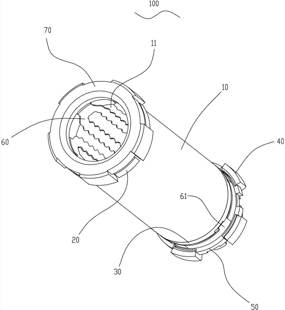
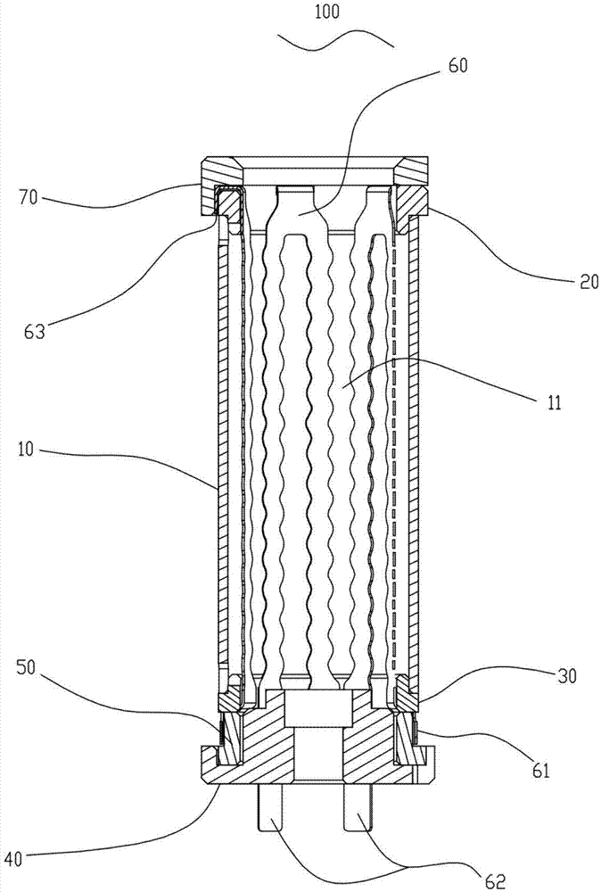
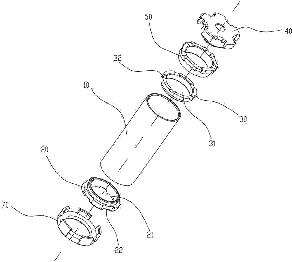
[0044] Such as figure 1 , figure 2 , image 3 As shown, this embodiment discloses a smoke generator 100 for combining with a power supply 200 to form a smoke suction device (such as Figure 10 ), which includes a support tube 10 made of a heat-resistant material, a plurality of heating elements 60 with a first end 63 and a second end 64 arranged in the support tube, a first bracket 20 with an air outlet 21 and a The second bracket 30 of the air inlet 31, the first bracket 20 and the second bracket 30 are arranged at both ends of the support pipe 10, and the first bracket and the second bracket are all provided with a plurality of positioning parts, and the plurality of the The first ends of the heating elements are all erected on the first bracket and bent on the positioning part of the first bracket, and the second ends are all erected on the second bracket and bent at the positioning part of the second bracket. In part, the heating element 60 surrounds a cavity 11 suita...

Embodiment 2

[0062] Described assembly method comprises the following steps:

[0063] a. Fix the first bracket 20 and the second bracket 30 at both ends of the support tube 10;

[0064] b. Sleeve the support tube 10 obtained in step a on an assembly rod 91 suitable for passing through the support tube 10;

[0065] c. Insert the first end 63 of the heating element 60 along the end of the second bracket 30 from the gap between the support tube 10 and the assembly rod 91 until the first end 63 of the heating element 60 protruding from the end of the first bracket 20;

[0066]d. Bending the two ends of the heating element 60 on the positioning parts of the first bracket 20 and the second bracket 30 respectively, so as to fix the heating element 60;

[0067] e. Fix each heating element 60 on the first bracket 20 and the second bracket 30 along the circumferential direction of the support tube 10 in sequence, so that a plurality of heating elements 60 surround a cavity suitable for filling sol...


PUM


Abstract

The invention relates to a smoke generator assembling method. The smoke generator assembling method comprises the following steps: a, a first support (20) and a second support (30) are fixed to the two ends of a support tube (10); b, the support tube (10) obtained in the step a sleeves an assembly rod (91) suitable for penetrating the support tube (10); c, first ends (63) of heaters (60) are inserted into a clearance between the support tube (10) and the assembly rod (91) along the second support (30) end till the first ends (63) of the heaters (60) extends out from the first support (20) end; d, both ends of the heaters (60) are respectively bent on locating parts, so that the heaters (60) are fixed; and 6, all the heaters (60) are sequentially fixed in the circumferential direction of the support tube (10), so that a cavity (11) is defined by the heaters (60).The smoke generator assembling method has the advantages of simple and quick process, high production efficiency, low defective rate of end products and the like.

Description

technical field [0001] The invention relates to the field of smoking utensils, in particular to an assembly method of a smoke generator. Background technique [0002] Smoking not only endangers the health of smokers, but also pollutes the surrounding environment. In order to reduce the physical harm of smoking to smokers and reduce environmental pollution, people have developed an inhalation device that heats tobacco in a non-combustion manner to generate smoke. Compared with traditional cigarettes, the inhalation device can greatly reduce harmful substances (such as tar) inhaled into the human body by heating and drying solid tobacco products at a lower temperature, so this inhalation device is gradually being welcomed by smokers and consumers. Due to the above advantages, the new suction device, as a new type of smoking device, has become increasingly popular with consumers, but in the prior art, the heating structures inside most new types of cigarette smoking devices ar...

Claims


Application Information

Patent Timeline
Patent Type & Authority Applications(China)
IPC IPC(8): A24F47/00A24F40/20A24F40/46A24F40/70
CPCA24F40/20A24F40/70A24F40/46
Inventor 缪明明陈永宽汤建国郑绪东雷萍尚善斋向能军袁大林孙志勇杨柳朱东来廖晓祥李寿波杨继赵伟罗洪勇
Owner CHINA TOBACCO YUNNAN IND
Why Eureka
Try Eureka