
Guide apparatus of medium speed coal mill vane throat ring
A diversion device and coal grinding technology, which is applied in the field of mechanical components, can solve the problems of reducing the discharge rate of pebble coal, and achieve the effects of reducing the discharge rate, increasing the wind speed, and improving the pulverizing output
- Summary
- Abstract
- Description
- Claims
- Application Information
AI Technical Summary
Problems solved by technology
Method used
Image

Examples
Embodiment Construction
[0017] The present invention will be further described below in conjunction with accompanying drawing.
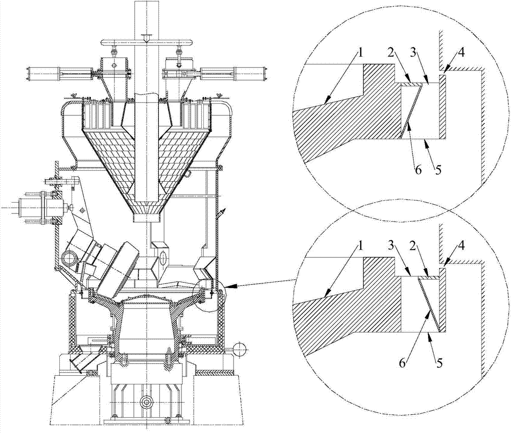
[0018] Such as figure 1 with figure 2 As shown, the deflector device of the medium-speed pulverizer air ring flow guide includes a deflector 6 .
[0019] A deflector 6 is added to the lower part of the existing coal mill wind ring flow ring 2 .
[0020] The upper end of the deflector 6 is fixed on the edge of the throttle ring 2 near the outlet 3 of the air ring, and the lower end is fixed on the edge of the inlet 5 of the air ring near the primary air chamber.
[0021] In order to better cooperate with the wind ring, the deflector 6 has the same upper end with the same circular arc as the wall at the throttle ring 2, and the same lower end with the same circular arc with the wall at the air ring inlet 5.
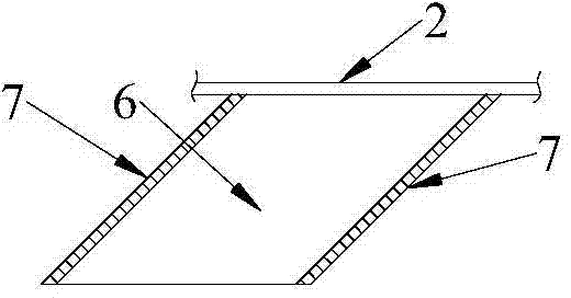
[0022] Such as figure 2 As shown, in order to cooperate with the swirl vanes 7 in the wind ring, the two sides of the deflector 6 should be inclined, and the incl...
PUM
 Abstract
Description
Claims
Application Information