Electromagnetic elutriation fine separation machine

A concentrator and elutriation technology, applied in magnetic separation, high-gradient magnetic separator, solid separation, etc., can solve problems such as intermittent fluctuations in the overflow liquid level, unfavorable adsorption of ferromagnetic minerals, and reduced recovery of concentrates , to achieve the effect of eliminating intermittent fluctuations, eliminating the phenomenon of ore running, and reducing the grade of tailings

Active Publication Date: 2015-07-15
SHANDONG HUATE MAGNET TECH
View PDF12 Cites 11 Cited by
  • Summary
  • Abstract
  • Description
  • Claims
  • Application Information

AI Technical Summary

Problems solved by technology

However, these existing magnetic separation equipments have more or less defects: the conventional permanent magnetic drum magnetic separator has obvious magnetic agglomeration phenomenon in the beneficiation process, and the range of improving the concentrate grade is limited; the magnetic field of the magnetic agglomerator is constant and cannot Adapt to the requirements of different ore properties and concentrate grades, and have defects such as running tails; every time the entire set of excitation coils of the magnetic separation column changes for one cycle, there will be a non-magnetic area in the upper overflow area, which will easily cause the overflow tailings to have higher magnetic iron grades. Affect concentrate recovery
Because the fixed coil is always energized, the adsorbed ferromagnetic minerals will become thicker and thicker, which is not conducive to the continued adsorption of ferromagnetic minerals in the later stage
[0006] At the same time, when the weight of the ferromagnetic minerals adsorbed is greater than the suction force of the magnetic field and the momentum of the rising water, they will slide down along the inner wall of the elutriation machine as a whole. During the sliding process, because the stable sorting environment inside the elutriation machine is destroyed, it will Most of the missing and chained iron ore minerals are washed out by the rising water flow, resulting in sudden overflow, causing intermittent fluctuations in the overflow liquid level, unstable overflow liquid level, and not conducive to effective tail control , leading to an increase in the magnetic iron content of the tailings, an increase in the grade of the tailings, and a decrease in the recovery rate of the concentrate
Therefore, the elutriation magnetic separator with only one fixed coil control mode is difficult to reasonably and effectively tail some mines, resulting in higher tailings grade, lower concentrate recovery rate, less stable control, and affected economic benefits.
[0007] At present, the diameter of the feeding pipe of the feeder of the elutriation magnetic separator is relatively small, generally equal to or smaller than the diameter of the closed inner cylinder, because the closer to the shaft diameter of the separation cylinder, the weaker the magnetic field strength, so the closer to the feeder The magnetic iron in the feed pipe is less likely to be captured by the magnetic field, resulting in an increase in the content of magnetic iron in the overflow tailings, which also results in higher tailings grades and lower concentrate recovery rates.
In addition, after the magnetite powder enters the feeder of the elutriation magnetic separator, it overflows directly from the drop pipe at the lower part of the feeder. After the material enters the sorting cylinder in this way, the bulk material is not uniform, which is not conducive to elutriation magnetic separation. Machine-to-concentrate beneficiation
[0008] In addition, the elutriation magnetic separator also has problems such as large water consumption, and the influence of the selection effect when the feed fluctuates.

Method used


Image

  • Electromagnetic elutriation fine separation machine
  • Electromagnetic elutriation fine separation machine
  • Electromagnetic elutriation fine separation machine

Examples


Embodiment 1

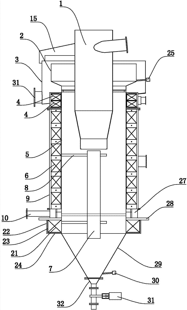
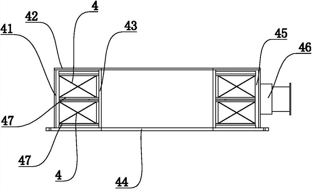
[0042] refer to figure 1 and figure 2 , the electromagnetic elutriation and selection machine of the present embodiment includes a sorting cylinder 5, a feeder 1 is arranged on the sorting cylinder 5, and an electromagnetic coil is arranged on the outer sleeve of the sorting cylinder 5, and the electromagnetic coil includes two stacked on the top up and down. There are three fixed coils 4 used alternately, the circulating coil 6 in the middle and the compensation coil 21 in the bottom. The bottom of the sorting cylinder 5 is provided with a water supply pipe 10, and the periphery of the sorting cylinder 5 corresponding to the water supply pipe is provided with a water inlet ring 27 connected to the inside of the sorting cylinder 5. Specifically, the lower outer wall of the sorting cylinder 5 is fixed with a certain thickness. Tray 28, the tray 28 is lower than the water supply pipe 10 for a certain distance, the water inlet ring 27 is arranged on the periphery of the sorting...

Embodiment 2

[0046] refer to image 3 , Figure 4 , Figure 5 , Figure 6 , Figure 7 as well as Figure 8 , the structure of the electromagnetic elutriation and concentration machine of embodiment two is basically the same as the structure of the electromagnetic elutriation and concentration machine of embodiment one, the difference is that: the feeder 1 includes a vertically arranged cylindrical ore feeding tube 11. The ore feeding pipe 12 is provided on the ore feeding pipe 11, and the ore feeding pipe 12 is arranged along the tangent line of the ore feeding pipe 11. A number of spiral blades 16 are fixed on the inner wall of the ore feeding pipe 11. The starting end of the spiral blade 16 corresponds to the feeder. Mine pipe 12 is set.

[0047] There is a conical body 13 in the bottom of the ore feeding tube 11, and there is a discharge gap 17 between the conical surface of the conical body 13 and the inner wall of the ore feeding tube 11. In the bottom of the cylinder 11, the co...

Embodiment 3

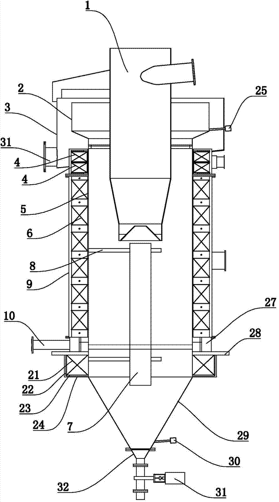
[0057] refer to Figure 9 , the structure of the electromagnetic elutriation and selection machine of embodiment three is basically the same as the structure of the electromagnetic elutriation and selection machine of embodiment two, the difference is that: the periphery of the bottom of the sorting cylinder 5 is provided with an annular water inlet ring 27, The water inlet ring 27 is provided with a water inlet pipe mouth, and the water inlet pipe mouth is connected with the water supply pipe 10 tangentially along the outer circle of the water inlet ring 27; the annular area corresponding to the water inlet ring 27 on the sorting cylinder 5 is provided with water inlets at intervals 26. The opening size of the water inlet 26 gradually increases from the place close to the water inlet to the place far away from the water inlet.

[0058] An annular pressure stabilizing buffer plate 271 is fixed at the inner bottom of the annular water inlet ring 27 , and the height of the annul...


PUM


Abstract

The invention discloses an electromagnetic elutriation fine separation machine. The electromagnetic elutriation fine separation machine comprises a separation tube, a feeding device is arranged on the separation tube, a water inlet device is arranged outside the separation tube in a communicated mode, the separation tube is sleeved with an electromagnetic coil which comprises a circulation coil in the middle, and the electromagnetic coil further comprises two fixed coils which are vertically stacked at the top and used alternatively. According to the electromagnetic elutriation fine separation machine, the grade of tailings is low, the recovery rate of concentrate is high, feeding is even, and the overflow liquid level is stable.

Description

technical field [0001] The invention relates to the technical field of magnetic separator equipment, in particular to an electromagnetic elutriation and selection machine. Background technique [0002] The equipment used to improve the grade of concentrate in the magnetite concentrator mainly includes conventional permanent magnet drum magnetic separator, magnetic concentrator, magnetic separation column, and elutriation magnetic separator. However, these existing magnetic separation equipments have more or less defects: the conventional permanent magnetic drum magnetic separator has obvious magnetic agglomeration phenomenon in the beneficiation process, and the range of improving the concentrate grade is limited; the magnetic field of the magnetic agglomerator is constant and cannot Adapt to the requirements of different ore properties and concentrate grades, and have defects such as running tails; every time the entire set of excitation coils of the magnetic separation col...

Claims


Application Information

Patent Timeline
Patent Type & Authority Applications(China)
IPC IPC(8): B03B7/00B03B5/00B03C1/033
CPCB03B5/00B03B7/00B03C1/0335
Inventor 孟祥军刘茂堂刘世昌刘风亮王兆连刘岩赵毅
Owner SHANDONG HUATE MAGNET TECH
Why Eureka
Try Eureka