Electromagnetic elutriation and selection machine
A concentrator and elutriation technology, applied in magnetic separation, high-gradient magnetic separator, solid separation, etc., can solve the problems of intermittent fluctuation of overflow liquid level, lower concentrate recovery rate, unfavorable adsorption of ferromagnetic minerals, etc. , to achieve the effect of eliminating intermittent fluctuations, preventing excessive knot chains, and eliminating the phenomenon of mine running
- Summary
- Abstract
- Description
- Claims
- Application Information
AI Technical Summary
Problems solved by technology
Method used
Image
Examples
Embodiment 1
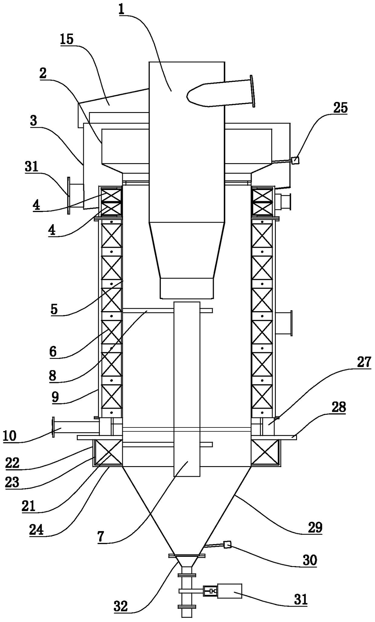
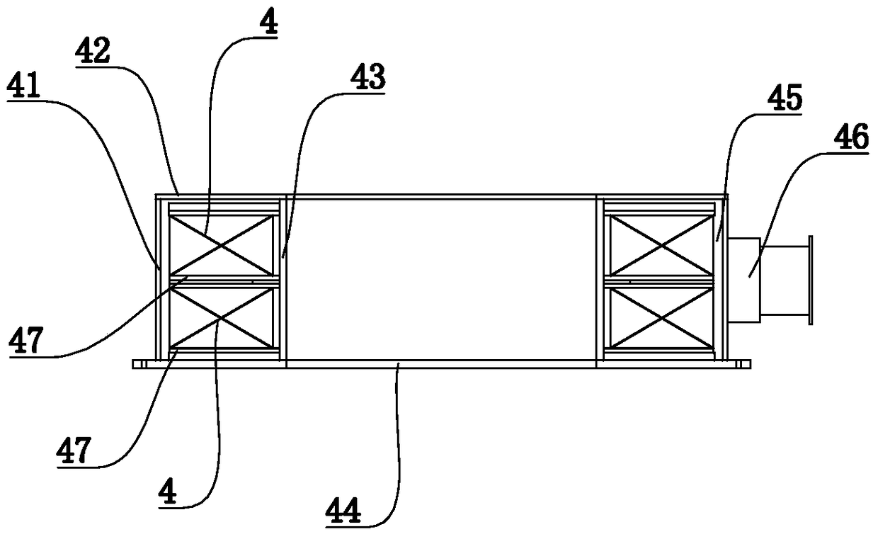
[0042] refer to figure 1 and figure 2 , the electromagnetic elutriation and selection machine of the present embodiment includes a sorting cylinder 5, a feeder 1 is arranged on the sorting cylinder 5, and an electromagnetic coil is arranged on the outer sleeve of the sorting cylinder 5, and the electromagnetic coil includes two stacked on the top up and down. There are three fixed coils 4 used alternately, the circulating coil 6 in the middle and the compensation coil 21 in the bottom. The bottom of the sorting cylinder 5 is provided with a water supply pipe 10, and the periphery of the sorting cylinder 5 corresponding to the water supply pipe is provided with a water inlet ring 27 connected to the inside of the sorting cylinder 5. Specifically, the lower outer wall of the sorting cylinder 5 is fixed with a certain thickness. Tray 28, the tray 28 is lower than the water supply pipe 10 for a certain distance, the water inlet ring 27 is arranged on the periphery of the sorting...
Embodiment 2
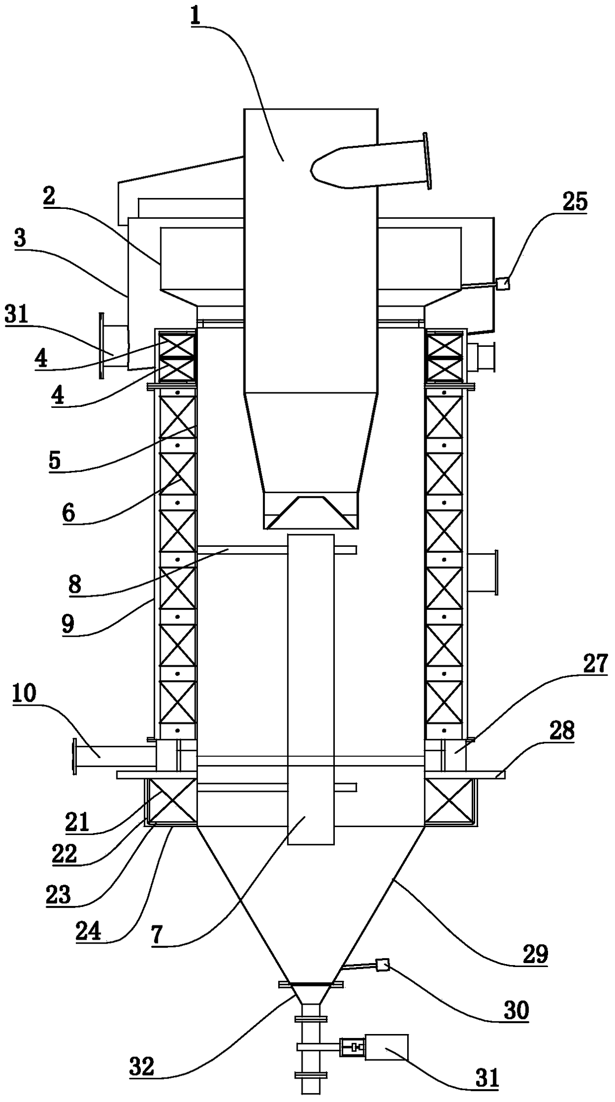
[0046] refer to image 3 , Figure 4 , Figure 5 , Image 6 , Figure 7 as well as Figure 8 , the structure of the electromagnetic elutriation and concentration machine of embodiment two is basically the same as the structure of the electromagnetic elutriation and concentration machine of embodiment one, the difference is that: the feeder 1 includes a vertically arranged cylindrical ore feeding tube 11. The ore feeding pipe 12 is provided on the ore feeding pipe 11, and the ore feeding pipe 12 is arranged along the tangent line of the ore feeding pipe 11. A number of spiral blades 16 are fixed on the inner wall of the ore feeding pipe 11. The starting end of the spiral blade 16 corresponds to the feeder. Mine pipe 12 is set.
[0047] There is a conical body 13 in the bottom of the ore feeding tube 11, and there is a discharge gap 17 between the conical surface of the conical body 13 and the inner wall of the ore feeding tube 11. In the bottom of the cylinder 11, the con...
Embodiment 3
[0057] refer to Figure 9 , the structure of the electromagnetic elutriation and selection machine of embodiment three is basically the same as the structure of the electromagnetic elutriation and selection machine of embodiment two, the difference is that: the periphery of the bottom of the sorting cylinder 5 is provided with an annular water inlet ring 27, The water inlet ring 27 is provided with a water inlet pipe mouth, and the water inlet pipe mouth is connected with the water supply pipe 10 tangentially along the outer circle of the water inlet ring 27; the annular area corresponding to the water inlet ring 27 on the sorting cylinder 5 is provided with water inlets at intervals 26. The opening size of the water inlet 26 gradually increases from the place close to the water inlet to the place far away from the water inlet.
[0058] An annular pressure stabilizing buffer plate 271 is fixed at the inner bottom of the annular water inlet ring 27 , and the height of the annul...
PUM
 Abstract
Description
Claims
Application Information
 - R&D
- Intellectual Property
- Life Sciences
- Materials
- Tech Scout
- Unparalleled Data Quality
- Higher Quality Content
- 60% Fewer Hallucinations
Browse by: Latest US Patents, China's latest patents, Technical Efficacy Thesaurus, Application Domain, Technology Topic, Popular Technical Reports.
© 2025 PatSnap. All rights reserved.Legal|Privacy policy|Modern Slavery Act Transparency Statement|Sitemap|About US| Contact US: help@patsnap.com


