First intermediate roll swing arm type bracket system of twenty-high roll mill

A 20-high rolling mill and 20-high rolling technology, applied in the direction of metal rolling stand, metal rolling mill stand, metal rolling, etc., can solve the problems of difficult assembly and debugging, big drawbacks, long time for roll change, etc. Fast and efficient roll change, easy operation and compact structure

Active Publication Date: 2015-07-15
CHINA NAT HEAVY MACHINERY RES INSTCO
View PDF11 Cites 2 Cited by
  • Summary
  • Abstract
  • Description
  • Claims
  • Application Information

AI Technical Summary

Problems solved by technology

However, the structure of the tower-type roll system of the 20-high rolling mill is complex. This tower-type roll system is generally driven by the second intermediate roll, while the two ends of the first intermediate roll are in a suspended state. There is no support at both ends of the first intermediate roll, which cannot realize the normal operation of the rolling mill. In the operation of opening the roll gap of the belt threading, the upper intermediate roll will fall on the working roll due to its own weight. There are two methods commonly used in the existing technology to solve this problem.
[0003] A suspension balance method is used to suspend the two ends of the intermediate roll with springs to balance the weight of the intermediate roll itself. This method is convenient and reliable on the operation side, but for the transmission side, since this type of rolling mill basically uses the second intermediate roll The transmission and suspension springs often interfere with the transmission shaft of the second intermediate roller from the spatial structure, which makes it difficult to assemble and debug the method in practice. In addition, when changing the first intermediate roller, this solution requires manual inspection from the operating side every time. Detour to the transmission side to remove the suspension spring, and then install it after changing the rollers. These have brought great inconvenience to normal production, and there are potential safety hazards, resulting in a long roller changing time.
[0004] In another method, support blocks are designed on the front and rear doors of the rolling mill. When the rolling mill is working, the front and rear doors are closed to support both ends of the first intermediate roll. Because this method limits the axial movement of the first intermediate roll in space, the two The first intermediate roll lateral movement of the ten-high rolling mill, which is an important means of controlling the shape of the plate, cannot be realized, and its disadvantages are relatively large. In addition, this method can only ensure the support of the intermediate roll when the front and rear doors are closed. When the front door is open, it still cannot be moved middle roller support
The above two existing technical solutions have their own advantages and disadvantages, but taken together, they still cannot meet the high-efficiency, safe, and easy-to-operate production requirements of the 20-high rolling mill.

Method used


Image

  • First intermediate roll swing arm type bracket system of twenty-high roll mill

Examples


Embodiment 1

[0017] This embodiment provides a swing-arm bracket system for the first intermediate roll of a 20-high rolling mill, which consists of two swing-arm brackets that are vertically symmetrical about the center of the 20-high rolling mill and arranged under the two first intermediate rolls device composition;

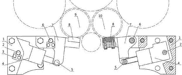
[0018] The swing arm bracket device includes a swing arm bracket 7 arranged below the first intermediate roller, a fixed bracket 1 connected to the swing arm bracket 7 through a swing arm hinge shaft 6, and the fixed bracket 1 is arranged on the twenty-roller On the transmission side of the press frame, the fixed bracket 1 is provided with a swing arm cylinder 4, the tail of the swing arm cylinder 4 is hingedly mounted on the fixed bracket 1 through the cylinder hinge shaft 2, and the rod end of the swing arm cylinder 4 passes through the cylinder rod The connecting shaft 5 is hinged with the swing arm bracket 7 .

[0019] The implementation process of this embodiment:

...

Embodiment 2

[0022] On the basis of Embodiment 1, a lock plate 3 is provided at one end of the cylinder hinge shaft 2 of the swing arm oil cylinder 4, which can realize axial limit. A cushion block 8 is provided at the junction of the swing arm bracket 7 and the first intermediate roller, so that the cushion block 8 directly contacts the left first intermediate roller 9 and the right first intermediate roller 10 to avoid wear of the two first intermediate rollers .

Embodiment 3

[0024] This embodiment provides a figure 1 In the swing arm bracket system of the first intermediate roller of the twenty-roller press shown, a swing arm bracket 7 is arranged under each first intermediate roll, and a spacer 8 is fixedly installed on each swing arm bracket 7. The spacer 8 is in direct contact with the first left middle roller 9 and the first right middle roller 10, the swing arm bracket 7 is hinged with the rod end of the swing arm oil cylinder 4, and the stretching of the oil cylinder rod drives the swing arm bracket 7 to swing around the swing arm hinge shaft 6 , the tail of the swing arm oil cylinder 4 is hingedly mounted on the fixed bracket 1 through the cylinder hinge shaft 2, and one end of the cylinder hinge shaft 2 has a lock plate 3 axially limited, and the fixed bracket 1 is fixedly installed on the transmission side of the rolling mill frame. The first left middle roller 9 and the first right middle roller 10 are each supported by the above-mention...


PUM


Abstract

The invention belongs to the technical field of plate and strip rolling, and specifically relates to a first intermediate roll swing arm type bracket system of a twenty-high roll mill. The system consists of two swing arm type bracket devices which are vertically symmetric about the center of the twenty-high roll mill and arranged below two first intermediate rolls, and the swing arm type bracket devices comprise swing arm brackets arranged below the first intermediate rolls and fixed supports which are connected with the swing arm brackets by virtue of swing arm hinged shafts; the fixed supports are arranged on a driving side of a twenty-high roll mill rack, the fixed supports are provided with swing arm oil cylinders, the tail parts of the swing arm oil cylinders are articulated with the fixed supports by virtue of cylinder body hinged shafts, and rod ends of the swing arm oil cylinders are hinged with the swing arm brackets by virtue of cylinder rod connection shafts. The bracket system can swing the brackets during roll replacement, the intermediate rolls are enable to fall without performing manual operation on the mechanism at the driving side of the twenty-high roll mill by workers, and the intermediate roll replacement is rapidly and efficiently realized.

Description

technical field [0001] The invention belongs to the technical field of plate and strip rolling, and in particular relates to a swing-arm bracket system for the first intermediate roll of a twenty-high rolling mill. Background technique [0002] In the field of metal strip rolling, the 20-high integral stand mill is widely used in the production of stainless steel strips, silicon steel strips and precision alloy strips due to its small diameter of work rolls, high rigidity of the roll system, and high pass reduction rate. . However, the structure of the tower-type roll system of the 20-high rolling mill is complex. This tower-type roll system is generally driven by the second intermediate roll, while the two ends of the first intermediate roll are in a suspended state. There is no support at both ends of the first intermediate roll, which cannot realize the normal operation of the rolling mill. In the roll gap opening operation of threading, the upper intermediate roll will ...

Claims


Application Information

Patent Timeline
Patent Type & Authority Applications(China)
IPC IPC(8): B21B31/10
Inventor 王大号刘云飞王斌魏志毅
Owner CHINA NAT HEAVY MACHINERY RES INSTCO
Why Eureka
Try Eureka