Oblique Composite High-frequency Vibration Drawing Method for Metal Profiles

A high-frequency vibration, metal profile technology, applied in the direction of fluid using vibration, etc., can solve the problems of many drawing passes, easy mold wear, microscopic surface defects, etc., to reduce drawing passes, improve life and use efficiency. , the effect of reducing energy consumption

Inactive Publication Date: 2017-04-12
NANHUA UNIV
View PDF5 Cites 0 Cited by
  • Summary
  • Abstract
  • Description
  • Claims
  • Application Information

AI Technical Summary

Problems solved by technology

[0002] Most of the traditional cold-drawn metal profiles are directly drawn by drawing dies. During the drawing process, due to the large friction coefficient between the metal profiles and the drawing dies, the corresponding resistance is also large, so the required drawing force is large and the drawing There are many drawing passes, and the mold is easy to wear and has a low service life. At the same time, there are scratches and microscopic cracks on the surface of the drawn metal profile; Vibration excitation, that is, the friction coefficient between the metal profile and the drawing die is reduced by using horizontal ultrasonic vibration excitation for the drawing die, but since the drawing die only generates vibration along the horizontal direction of the metal profile, the metal profile The friction coefficient between the drawing die and the drawing die is still large, and there are still microscopic surface defects on the surface of the drawn metal profile

Method used


Image

  • Oblique Composite High-frequency Vibration Drawing Method for Metal Profiles
  • Oblique Composite High-frequency Vibration Drawing Method for Metal Profiles
  • Oblique Composite High-frequency Vibration Drawing Method for Metal Profiles

Examples


Embodiment Construction

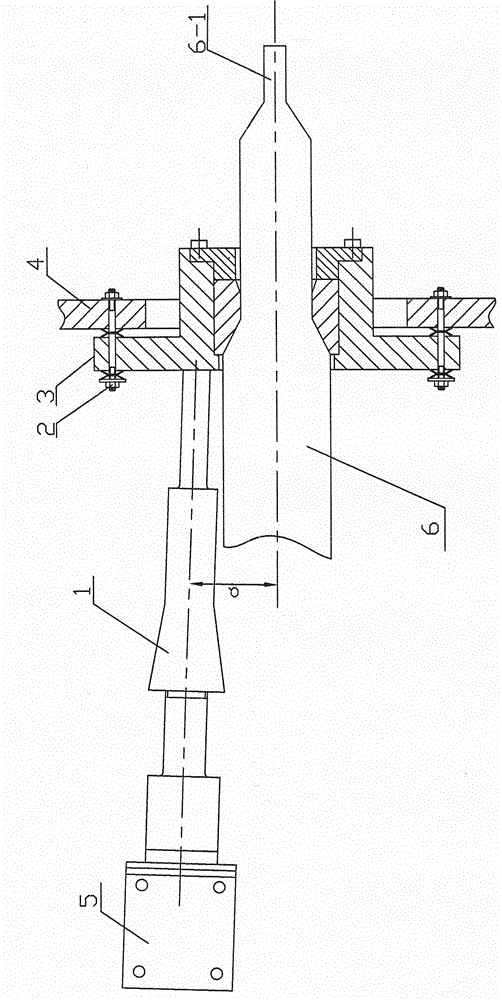
[0019] A method for drawing metal profiles using oblique composite high-frequency vibrations. During the drawing process, composite high-frequency vibrations along the horizontal and vertical directions of the metal profiles 6 are generated by a pair of drawing dies 3 through an oblique composite high-frequency vibration device 1. Vibration reduces the coefficient of friction between the metal profile 6 and the drawing die 3 .

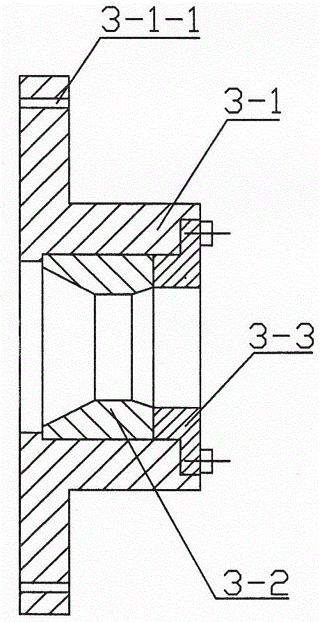
[0020] Elastic connection is adopted between the drawing die 3 and the base die base 4 on the drawing machine, and the drawing die 3 is connected with the base die base 4 on the drawing machine through six elastic connecting devices 2 .

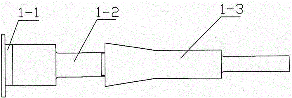
[0021] The oblique composite high-frequency vibration device 1 is fixed on the drawing machine through the mounting plate 5, and the secondary horn 1-3 in the oblique composite high-frequency vibration device 1 and the drawing die base 3- The end faces of 1 are fastened and connected, the angle a between the axis of t...


PUM


Abstract

The invention relates to a method for drawing metal section in an inclined composite high-frequency vibration manner. An inclined composite high-frequency vibration device is used for generating composite high-frequency vibration in a horizontal direction and a vertical direction of the metal section to act on a drawing die in a drawing process, thus, the friction coefficient between the metal section and the drawing die is reduced; the drawing die is elastically connected with a die holder of the machine base of a drawing machine, the composite high-frequency vibration device is fixed on a drawing machine tool by a mounting plate, a secondary amplitude-change pole in the composite high-frequency vibration device is fastened on and connected with the end surface of a drawing die holder, an included angle alpha between the axis of the composite high-frequency vibration device and the axis of the drawing die is 5-15 degrees, a piezoelectric ceramic transducer in the composite high-frequency vibration device generates high-frequency excitation frequency to drive a primary amplitude-change pole to vibrate at high frequency, and then the secondary amplitude-change pole vibrates at high frequency under the driving action of the primary amplitude-change pole; therefore, the drawing die is driven to do composite high-frequency vibration in the horizontal direction and the vertical direction.

Description

technical field [0001] The invention relates to the technical field of plastic processing of metal materials, in particular to a method for drawing metal profiles by oblique composite high-frequency vibration. Background technique [0002] Most of the traditional cold-drawn metal profiles are directly drawn by drawing dies. During the drawing process, due to the large friction coefficient between the metal profiles and the drawing dies, the corresponding resistance is also large, so the required drawing force is large and the drawing There are many drawing passes, and the mold is easy to wear and has a low service life. At the same time, there are scratches and microscopic cracks on the surface of the drawn metal profile; Vibration excitation, that is, the friction coefficient between the metal profile and the drawing die is reduced by using horizontal ultrasonic vibration excitation for the drawing die, but since the drawing die only generates vibration along the horizontal...

Claims


Application Information

Patent Timeline
Patent Type & Authority Patents(China)
IPC IPC(8): B21C1/02B06B1/06
CPCB06B1/0644B21C1/02
Inventor 周炬苏金英胡良斌焦铬
Owner NANHUA UNIV
Why Eureka
Try Eureka