Piler with traction type lifting mechanism

A stacker and traction machine technology is applied in the stacker field to achieve the effects of reducing manufacturing costs, saving costs and low energy consumption

Active Publication Date: 2015-07-15
JIASNGSU GAOKE LOGISTICS TECH CO LTD
View PDF8 Cites 13 Cited by
  • Summary
  • Abstract
  • Description
  • Claims
  • Application Information

AI Technical Summary

Problems solved by technology

[0006] The existing technology can either realize the convenient installation and maintenance of the counterweight, or can realize the smooth operation of the counterweight and reduce the noise, but cannot meet these two requirements at the same time

Method used


Image

  • Piler with traction type lifting mechanism
  • Piler with traction type lifting mechanism
  • Piler with traction type lifting mechanism

Examples


no. 1 Embodiment approach

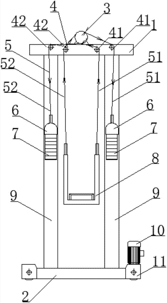
[0035] like figure 1 As shown, a stacker with a traction-type lifting mechanism includes a traction machine 3, a traction wire rope 5, an upper beam 1, a column 9, a lower beam 2, a cargo platform 8, a counterweight 7, and a travel motor 10 , walking wheel 10, fixed pulley 4, wherein column 9 components include two columns parallel to each other, the upper ends of two columns 9 are connected by upper beam 1, the lower end is connected by lower beam 2, upper beam 1, lower beam 2 and two The root column 9 constitutes the frame structure of the stacker. The traction machine 3, the traction wire rope 5, the counterweight 7, the fixed pulley 4, and the loading platform 8 together constitute a traction type lifting mechanism.

[0036] The upper beam 1 is provided with a fixed pulley 4, and one end of the traction wire rope 5 is connected with the loading platform 8, and the other end is connected with the counterweight 7 after bypassing the fixed pulley 4 and the traction machine 3...

no. 2 Embodiment approach

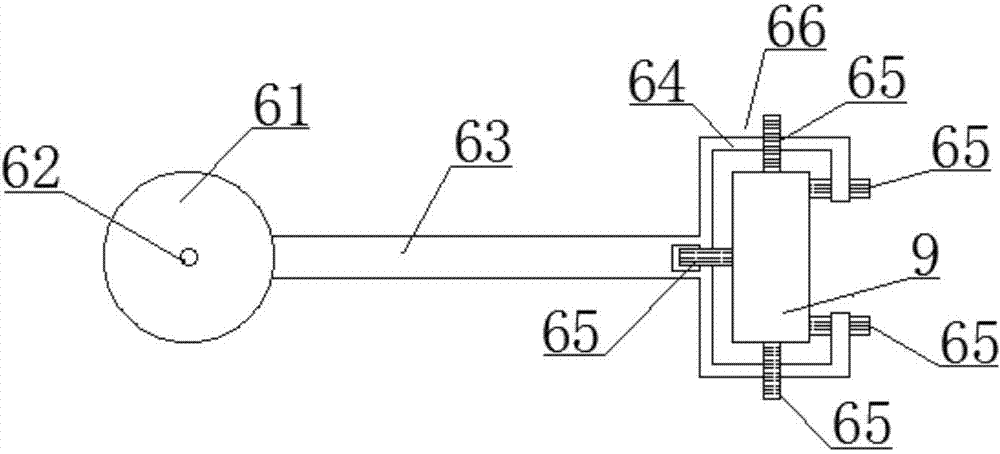
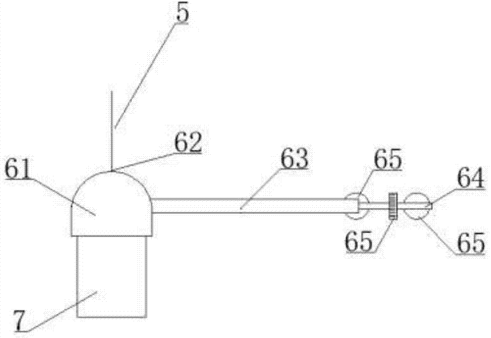
[0065] like Figure 4 As shown, a stacker with a traction type lifting mechanism includes a traction machine 3, a traction wire rope 5, an upper beam 1, a column 9, a lower beam 2, a cargo platform 8, a counterweight 7, and a traveling motor 10. , the walking wheel 10, the fixed pulley 4, wherein the column 9 assembly includes two columns arranged in parallel with each other, the upper ends of the two columns 9 are connected by the upper beam 1, the lower end is connected by the lower beam 2, the upper beam 1, the lower beam 2 and the two The root column 9 constitutes the stacker frame structure. The traction machine 3 includes a traction sheave, the counterweight block 7 is located outside the column 9 , and the counterweight block 7 is provided with a guide mechanism.

[0066] Preferably, the guiding mechanism includes a counterweight sleeve 61, a support rod 63, and a limiting mechanism 66. The bottom of the counterweight sleeve 61 is open, the upper end is a circular arc ...


PUM


Abstract

The invention discloses a piler with a traction type lifting mechanism. The piler with the traction type lifting mechanism comprises a tractor, a traction steel wire rope, an upper cross beam, stand columns, a lower cross beam, cargo carrying tables, clump weights, a walking motor, walking wheels and fixed pulleys, wherein the stand columns are two columns which are mutually arranged in parallel; the upper ends of the two stand columns are connected by the upper cross beam, and the lower ends of the stand columns are connected by the lower cross beam; the upper cross beam is provided with the fixed pulleys; one end of the traction steel wire rope is connected with the cargo carrying tables, and the other end of the traction steel wire rope bypasses one fixed pulley and the tractor and is then connected with the clump weights; the cargo carrying tables vertically move along the stand columns; the clump weights are positioned on the outer sides of the stand columns; each clump weight is provided with a shifting guide mechanism. According to the piler with the traction type lifting mechanism, the stable operation of all clump weights can be simultaneously realized, noise is lowed, and meanwhile, the clump weights can be conveniently installed and repaired.

Description

technical field [0001] The invention relates to the field of logistics automation machinery, in particular to a stacker with a traction-type lifting mechanism. Background technique [0002] Stacker is a kind of machinery commonly used in logistics automated warehouses. [0003] When the earlier stacker was working, when the loading platform (or fork) was lowered with load or empty, there was no corresponding storage method for its gravitational potential energy, which caused a large amount of electric energy to be consumed when the load was raised. In order to meet the energy-saving requirements of the development of modern society, there are already some stackers equipped with counterweights. [0004] However, the stacker needs to walk horizontally, so the counterweight device will inevitably shake and generate noise. Generally, the counterweight device needs to be installed inside the column and walk up and down along the inner wall of the column, or a separate guide rail...

Claims


Application Information

Patent Timeline
Patent Type & Authority Applications(China)
IPC IPC(8): B65G57/32
CPCB65G57/32B65G2201/02B65G2814/0304
Inventor 谢明杨树人施红玲金海涛李纯
Owner JIASNGSU GAOKE LOGISTICS TECH CO LTD
Why Eureka
Try Eureka