Compact three-phase separation method and device

A technology of three-phase separation and separation method, which is applied in the field of compact three-phase separation and devices, which can solve problems such as insufficient air intake, insufficient swirl field strength, and influence on oil removal effect, and achieve reasonable generation and distribution, and device structure Compact, performance-efficient effect

Active Publication Date: 2015-07-15
EAST CHINA UNIV OF SCI & TECH
View PDF7 Cites 19 Cited by
  • Summary
  • Abstract
  • Description
  • Claims
  • Application Information

AI Technical Summary

Problems solved by technology

[0004] In the CFU patents, in terms of the generation and injection of microbubbles, most of the patents adopt the method of setting a gas-liquid circulation circuit outside the tank, using a jet nozzle or a dissolved air pump to mix the circulating water and circulating gas with gas and liquid, and then pass through the tank. The distributor in the lower part releases the gas-liquid mixture to produce the air flotation effect. The disadvantage of this method is that the bubbles do not swirl in the separation chamber together with the feed, which makes it difficult to separate the tiny bubbles from the water, and the reinjection liquid hinders The normal form of the swirl field in the separation chamber is eliminated; in terms of the generation of the swirl field, most patents use the method of tangentially configured feed inlets or spiral guide vanes at the inlet to generate the swirl field, and at the same time through the reasonable Set to increase swirl strength
In the patent CN102083509A of VWS company, the method of generating gas-liquid mixing and swirling flow field is different. It uses a nozzle assembly to directly suck gas and liquid from the first fluid chamber and mix them. The discharge pipe is reasonably arranged to establish a swirling flow in the second fluid chamber. Compared with the previous method, the external gas-liquid circulation circuit and the spiral guide vane are omitted. The disadvantage is that the suction volume is not enough and the dispersion effect of the bubbles is not good due to the small suction pressure difference, and the lack of an inner cylinder will lead to The strength of the swirl field in the second fluid chamber is not enough, which affects the degreasing effect

Method used


Image

  • Compact three-phase separation method and device
  • Compact three-phase separation method and device
  • Compact three-phase separation method and device

Examples


Embodiment 1

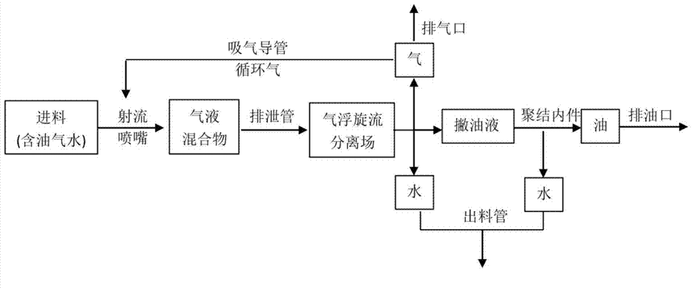
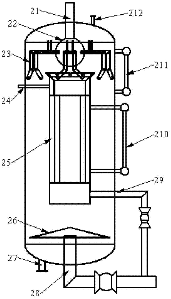
[0050] The process of degassing and deoiling separation of acidic water in a petrochemical sulfur plant adopts the method and device of the invention for pilot test, and adopts single-stage treatment. The schematic diagram of the three-phase separation process can be found in figure 1 , refer to the schematic diagram of the device structure Figure 2-5 :

[0051] The device includes a tank, a dispenser 22 , a jet ejector 23 , an inner barrel 25 and a bottom baffle 26 .

[0052] The diameter-to-height ratio of the tank body is 1:2 to 1:3, and it is equipped with a feed port, an exhaust port 212, an oil discharge port, a mud discharge port 27, a material discharge port 28, a coalescing water outlet 29, a pressure control gauge, The liquid level gauge 211 and the interface 512 of the interface level gauge of the inner cylinder.

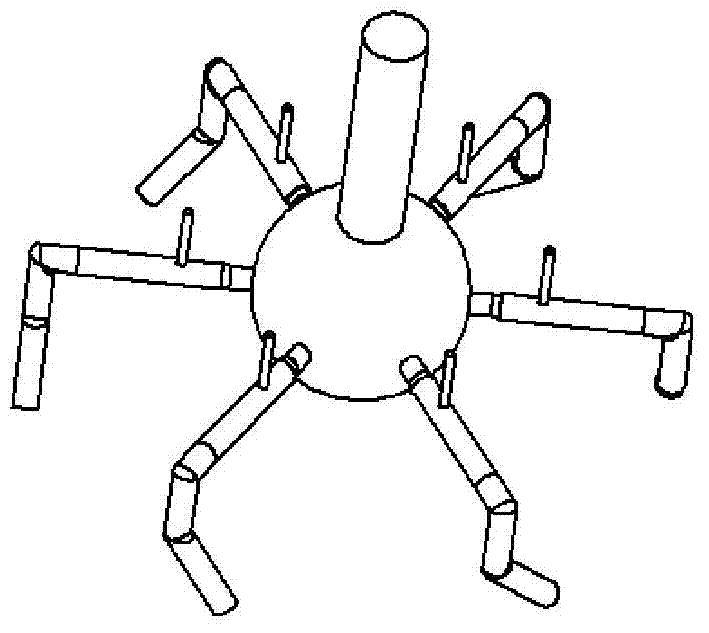
[0053] The distributor 22 is spherical or polygonal prism, and the outlets are evenly distributed around it horizontally.

[0054] The jet ejector 23...


PUM

PropertyMeasurementUnit
diameteraaaaaaaaaa

Abstract

The invention relates to a compact three-phase separation method and device. The method combines rotational flow, air floatation and coalescence technologies are combined and comprises establishment of an air floatation and rotational flow field in a separation cavity and coalescence separation of oil skimming solution in an inner cylinder. The device comprises a tank, a distributor, a jet flow educator, the inner cylinder, an inner coalescence part and a bottom baffle, wherein a jet flow nozzle is arranged at the front part of the jet flow educator, so that a gas-liquid mixture is formed; a drain pipe at the lower part is properly arranged, so that a rotational flow field is established in the separation cavity; the synergistic effect of air floatation and rotational flow separation is played; an oil skimming groove for skimming oil is at the upper end of the inner cylinder; the inner coalescence part in the interior can complete coalescence separation of the oil skimming solution and independent excretion of oil water; and, due to reasonable design of the size of the inner cylinder, the rotational flow field in the separation cavity is more reasonable to distribute. The device is free from external gas supply and gas-liquid auxiliary circulation facilities and has the advantages of compact structure, short residence time and small occupation area; and the device can be widely applied to degassing and removing oil in production water or sewage containing oil and gas.

Description

technical field [0001] The invention relates to a compact three-phase separation method and device combining swirling flow, air flotation and coalescence technology, which is suitable for the integrated treatment of degassing and deoiling of oil-containing and gas-containing production water or sewage, especially but not exclusively It is suitable for degassing and degreasing treatment of petrochemical acidic water. Background technique [0002] There are many conventional oil-water separation technologies, such as gravity sedimentation, cyclone separation, air flotation, coalescence, adsorption, membrane separation, etc., and the series combination of these conventional technologies and their equipment units to treat oily sewage often has high cost, high energy consumption, and occupation of The land is big. Gas-liquid separation is relatively easy. When the separation requirements are not high, simple methods such as decompression flash evaporation and centrifugal degassi...

Claims


Application Information

Patent Timeline
Patent Type & Authority Applications(China)
IPC IPC(8): C02F1/40C02F1/20C02F1/24C02F1/38
Inventor 杨强卢浩刘森竺嘉斌孙荣江许萧王朝阳
Owner EAST CHINA UNIV OF SCI & TECH
Why Eureka
Try Eureka