Air pressure type gas relief system
A pneumatic and air intake pipe technology, applied in the direction of machines/engines, internal combustion piston engines, mechanical equipment, etc., can solve problems such as the complex structure of the booster system, and achieve the effects of low fuel consumption, small pumping loss, and simple structure
- Summary
- Abstract
- Description
- Claims
- Application Information
AI Technical Summary
Problems solved by technology
Method used
Image
Examples
Embodiment
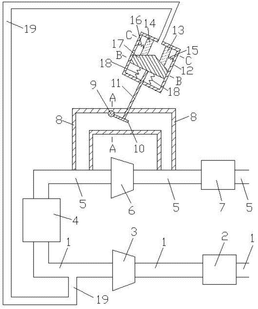
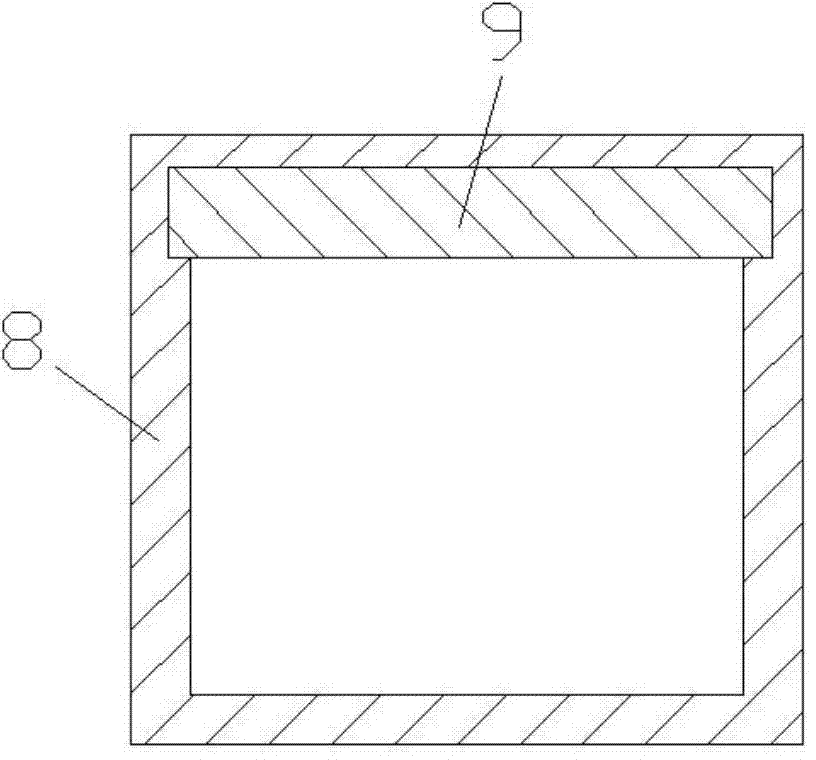
[0015] Examples of the present invention are Figure 1 to Figure 5 As shown, the present invention includes intake pipe 1, air filter 2, compressor 3, engine 4, exhaust pipe 5, turbine 6, muffler 7, air release pipe 8, rotating shaft 9, rotating plate 10, adjusting rod 11, control Cavity 12, first moving body 13, second moving body 14, first spring 15, second spring 16, third moving body 17, third spring 18, control pipe 19, air intake of engine 4 and air intake pipe 1 The air inlet and outlet of the exhaust pipe 5 are connected to the air outlet of the engine 4, the air filter 2 and the compressor 3 are connected to the intake pipe 1 in turn, the turbine 6 and the muffler 7 are connected to the exhaust pipe 5 in turn Above, the two ends of the air discharge pipe 8 are respectively connected with the exhaust pipes 5 before and after the turbine 6, the rotating shaft 9 is inlaid on the air discharging pipe 8, the rotating plate 10 is arranged in the air discharging pipe 8 and o...
PUM
 Abstract
Description
Claims
Application Information
 - R&D
- Intellectual Property
- Life Sciences
- Materials
- Tech Scout
- Unparalleled Data Quality
- Higher Quality Content
- 60% Fewer Hallucinations
Browse by: Latest US Patents, China's latest patents, Technical Efficacy Thesaurus, Application Domain, Technology Topic, Popular Technical Reports.
© 2025 PatSnap. All rights reserved.Legal|Privacy policy|Modern Slavery Act Transparency Statement|Sitemap|About US| Contact US: help@patsnap.com


