Liquid crystal display panel and device

一种液晶显示面板、液晶显示装置的技术,应用在仪器、非线性光学、光学等方向,能够解决高驱动电压、光效率低等问题,达到降低驱动电压、提高光效率、增强水平电场强度的效果

Active Publication Date: 2015-07-15
TCL CHINA STAR OPTOELECTRONICS TECH CO LTD +1
View PDF3 Cites 3 Cited by
  • Summary
  • Abstract
  • Description
  • Claims
  • Application Information

AI Technical Summary

Problems solved by technology

[0005] The purpose of the present invention is to provide a liquid crystal display panel and a device to solve the technical problems that the existing liquid crystal display panels require higher driving voltage and lower light efficiency

Method used


Image

  • Liquid crystal display panel and device
  • Liquid crystal display panel and device
  • Liquid crystal display panel and device

Examples


Embodiment Construction

[0034] The following descriptions of the various embodiments refer to the accompanying drawings to illustrate specific embodiments in which the invention may be practiced. The directional terms mentioned in the present invention, such as "up", "down", "front", "rear", "left", "right", "inside", "outside", "side", etc., are only for reference Additional schema orientation. Therefore, the directional terms used are for describing and understanding the present invention, not for limiting the present invention.

[0035] In the figures, structurally similar elements are denoted by the same reference numerals.

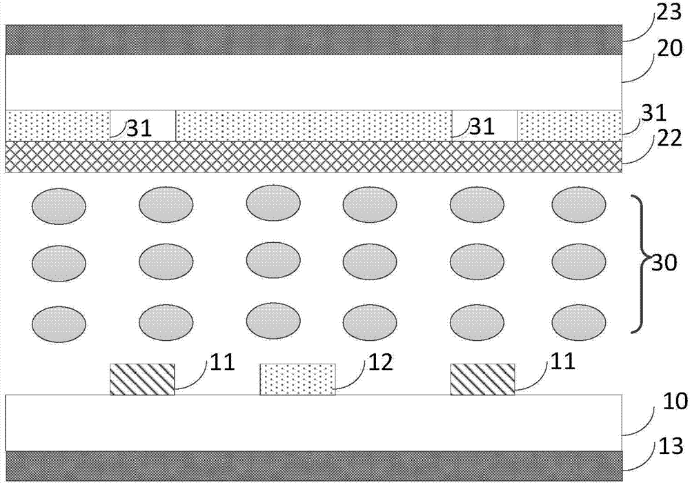
[0036] Please refer to image 3 , image 3 It is a schematic diagram of the structure of the liquid crystal display panel of the present invention.

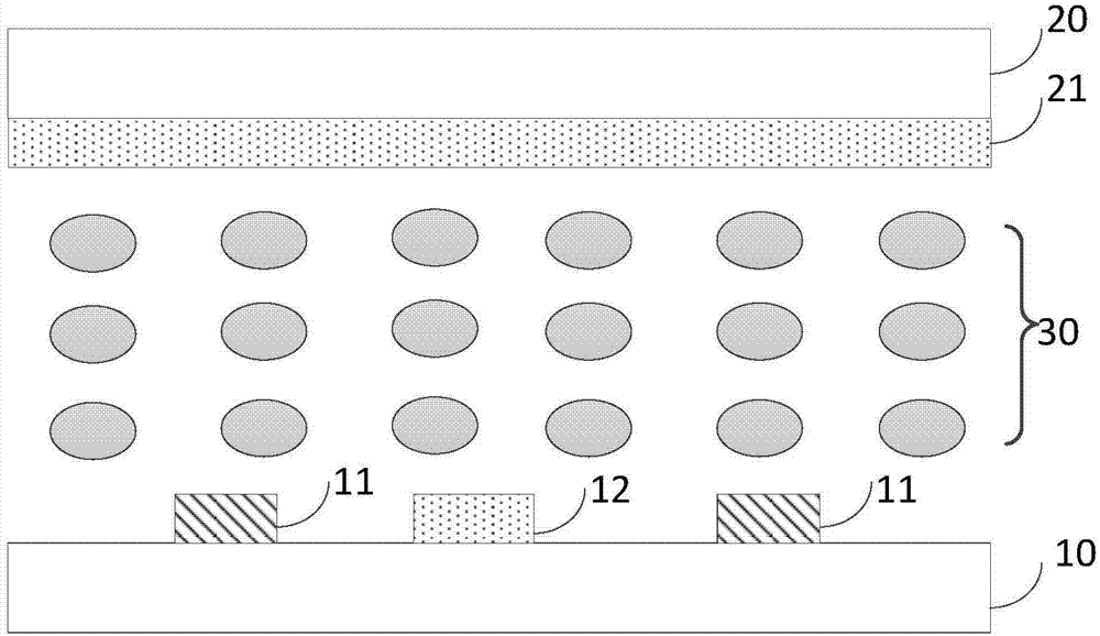
[0037] The liquid crystal display panel of the present invention includes: image 3 As shown, it includes a first substrate 20, which includes a first common electrode 31; a second substrate 10 disposed opposite to the fir...


PUM


Abstract

The invention provides a liquid crystal display panel and a device. The display panel comprises a first substrate, a second substrate and a liquid crystal layer, wherein the first substrate comprises a first common electrode; the second substrate is opposite to the first substrate and comprises a second common electrode and a pixel electrode; the liquid crystal layer is positioned between the first substrate and the second substrate; the projection of the pixel electrode on the first substrate and a graph of the first common electrode on the first substrate are not overlapped. According to the liquid crystal display panel and the device provided by the invention, a part, opposite to the pixel electrode, in the common electrode on the first substrate, is removed, and a part, which is not opposite to the pixel electrode, in the common electrode on the first substrate, is retained, so that a vertical electric field formed by the part, opposite to the first common electrode, of the pixel electrode, can be reduced, and the intensity of a horizontal electric field in the liquid crystal display panel is enhanced.

Description

technical field [0001] The present invention relates to the field of displays, in particular to a liquid crystal display panel and a device. Background technique [0002] Existing liquid crystal display panels such as figure 1 As shown, it includes a first substrate 20, a second substrate 10, and a liquid crystal layer 30; the first substrate 20 includes a first common electrode 21; the second substrate 10 is disposed opposite to the first substrate 20, and the second substrate 10 includes a second common electrode 12 and the pixel electrode 11; and the liquid crystal layer 30 is located between the first substrate 20 and the second substrate 10; the initial orientation of the liquid crystal molecules is vertical orientation. [0003] When a voltage is applied, a horizontal electric field is generated between the first common electrode 21 and the pixel electrode 11 not facing the pixel electrode 11, such as figure 2 The dotted box 102 is shown in the middle; however, the ...

Claims


Application Information

Patent Timeline
Patent Type & Authority Applications(China)
IPC IPC(8): G02F1/1343
CPCG02F1/134309G02F2201/123G02F2201/121G02F1/133357G02F1/134318G02F1/134381G02F1/133514G02F1/133528G02F1/134363
Inventor 谢畅
Owner TCL CHINA STAR OPTOELECTRONICS TECH CO LTD
Why Eureka
Try Eureka