A full-duplex system with high dynamic receiver and its method of use

A high-dynamic receiver, full-duplex technology, applied in the field of full-duplex systems, can solve the problem that the dynamic range of the self-interference signal exceeds the dynamic range of the receiver, and achieve the effect of simple structure and reduced dynamic range

Active Publication Date: 2017-03-29
UNIV OF ELECTRONICS SCI & TECH OF CHINA
View PDF6 Cites 0 Cited by
  • Summary
  • Abstract
  • Description
  • Claims
  • Application Information

AI Technical Summary

Problems solved by technology

[0007] The purpose of the present invention is to overcome the deficiencies of the prior art, provide a full-duplex system with a high dynamic receiver and its use method, and solve the problem that the dynamic range of the self-interference signal far exceeds the dynamic range of the receiver

Method used


Image

  • A full-duplex system with high dynamic receiver and its method of use
  • A full-duplex system with high dynamic receiver and its method of use

Examples


Embodiment 1

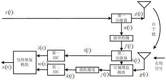
[0029] Such as figure 1 As shown, a full-duplex system with a high dynamic receiver, which includes a transmitting antenna module, a receiving antenna module, a first splitter, a waveform detection module, a second splitter, an adjustable gain device, and a receiving channel module , the first ADC, the second ADC and an envelope recovery module; the input end of the first splitter receives the signal to be sent, and the output end of the first splitter is connected with the transmitting antenna module and the waveform detection module respectively, and the waveform detection module The output end of the second splitter is connected with the second splitter, and the output end of the second splitter is connected with the first ADC and the adjustable gain device respectively, and the input end of the adjustable gain device is also connected with the output end of the receiving antenna module, adjustable The output terminal of the gain device is connected to the second ADC, the o...

Embodiment 2

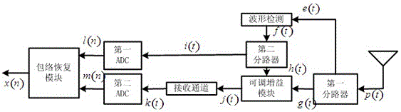
[0031] Such as figure 2 As shown, a full-duplex system with a high dynamic receiver, which includes a transmitting antenna module, a receiving antenna module, a first splitter, a waveform detection module, a second splitter, an adjustable gain device, and a receiving channel module , the first ADC, the second ADC and an envelope recovery module; the input terminal of the waveform detection module receives a signal output from one of the output terminals of the first splitter, and the output terminal of the waveform detection module is connected with the second branch The output end of the second splitter is connected with the first ADC and the adjustable gain device respectively, the input end of the adjustable gain device is also connected with the output end of the receiving antenna module, and the output end of the adjustable gain device is connected with the second ADC connection, the output end of the first ADC and the output end of the second ADC are connected to the en...


PUM


Abstract

The invention discloses a full-duplex system with a high dynamic receiver and its application method. The system includes a transmitting antenna module, a receiving antenna module, a first splitter, a waveform detection module, a second splitter, and an adjustable gain A device, a receiving channel module, a first ADC, a second ADC and an envelope recovery module; the output signal of the waveform detection module is an inverse function of the envelope of the input signal. The present invention performs gain adjustment through an adjustable gain module, and the output signal j(t) after the scaling process controlled by the gain control signal h(t) has the characteristic of significantly lower peak-to-average power ratio than the input signal g(t) , so j(t) significantly reduces the dynamic range requirements of the receiving channel compared to g(t); ideally, the output signal x(n) of the envelope recovery module is the discretized signal of g(t), which is equivalent to The receiver has completely received a high dynamic signal, which in turn means that the dynamics of the receiver has been greatly improved.

Description

technical field [0001] The invention relates to a system and method for converting analog signals to digital signals in the field of digital communication, in particular to a full-duplex system with a high dynamic receiver and its application method. Background technique [0002] In a full-duplex system, since the self-interference is much stronger than the received signal, it exceeds the dynamic range of the receiver, causing the receiver to saturate. To reduce the dynamic range of self-interfering signals, there are three main existing methods: [0003] 1. Reconstruct the self-interfering signal in the analog domain and then subtract it from the signal received by the antenna at the front end of the receiver. [0004] 2. Estimate the self-interference signal in the digital domain, up-convert the estimated signal to a radio frequency, and then subtract it from the signal received by the antenna at the front end of the receiver. [0005] 3. The transmitted signal and the r...

Claims


Application Information

Patent Timeline
Patent Type & Authority Patents(China)
IPC IPC(8): H04B1/40H04B1/12
Inventor 徐强鲁宏涛邵士海潘文生沈莹唐友喜
Owner UNIV OF ELECTRONICS SCI & TECH OF CHINA
Why Eureka
Try Eureka