Pneumatic tube needle installation machine

A technology for air pressure pipes and installation machines, which is applied to hand-held tools, manufacturing tools, etc., can solve the problems of increasing enterprises' dependence on unreliable factors, wasting parts and man-hours, and complicated tool design, so as to maintain production processes and maintain production stability. performance, reduce work pressure, and save materials

Inactive Publication Date: 2015-07-22
NANJING LINGYA AUTOMOBILE TECH RES INST
View PDF0 Cites 2 Cited by
  • Summary
  • Abstract
  • Description
  • Claims
  • Application Information

AI Technical Summary

Problems solved by technology

Raw materials are wasted after making mistakes, and unit man-hours of parts are wasted, which is not worth the candle
There are many uncertain factors in traditional tools. The tool design is too complicated and difficult to produce. A single product has many parts, time-consuming, and material-consuming characteristics. It is not suitable for enterprises with strong flexibility.
Once a problem occurs, the assembly line stops working or is replaced by inefficient labor, which greatly increases the company's dependence on unreliable factors

Method used


Image

  • Pneumatic tube needle installation machine

Examples


Embodiment Construction

[0010] The utility model will be further explained below in conjunction with the accompanying drawings and specific embodiments. It should be understood that the following specific embodiments are only used to illustrate the utility model and are not intended to limit the scope of the utility model.

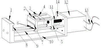
[0011] Such as figure 1 The present invention shown includes rack 1, fixing groove 2, sliding ruler 3, fixing screw 4, sliding bracket 5, bearing 6, lower file 7, upper file 8, guide rail 9, workbench 10, transmission rod 11, pneumatic device 12, air guide tube 13, fixing screw 14. The workbench 10 is composed of a base and front and rear baffles, the rack 1 is horizontally located on the upper edge of the front baffle of the workbench 10, and the upper file 8 is horizontally located in the concave groove above the front baffle of the workbench 10. Described sliding bracket 5 is made up of platform and front and rear vertical surface, and the platform of sliding bracket 5 is pr...


PUM


Abstract

The invention relates to a pneumatic tube needle installation machine. The pneumatic tube needle installation machine is characterized by comprising a rack, fixing grooves, a sliding push ruler, fixing screws, a sliding support, bearings, a lower file, an upper file, guide rails, a working table, a transmission rod, a pneumatic device, air guiding pipes and assembling screws, wherein power is provided by the pneumatic device to push the sliding support to impact with the rack along the guide rails so that tube needles fixed to the rack and a liquid crystal display fixed to the sliding support can be clamped together, and meanwhile the redundant parts of the tube needles are cut off by means of the dislocation caused when the upper file and the lower file impact with each other. According to the pneumatic tube needle installation machine, the redundant parts of the tube needles can be cut off when the tube needles are installed for the liquid crystal display, power is supplied through pushing of the pneumatic device instead of the general manual pushing, production efficiency is improved, and the workload is reduced.

Description

technical field [0001] The invention relates to a tube needle installation device, in particular to a pneumatic tube needle installation machine. Background technique [0002] In the prior art, there are many vacancies, a waste of man-hours, complicated procedures, and strong work difficulty. There are large errors in the traditional pin installation technology, wasting man-hours, complicated procedures, and very difficult work. Traditional manual work has strong requirements on workers' skills, and the error rate will greatly increase during high-intensity work. Raw materials are wasted after making mistakes, and unit man-hours of parts are wasted, which is not worth the candle. There are many uncertain factors in traditional tools. The tool design is too complicated and difficult to produce. A single product has the characteristics of multiple parts, time-consuming, and material-consuming. It is not suitable for enterprises with strong flexibility. Once a problem occurs...

Claims


Application Information

Patent Timeline
Patent Type & Authority Applications(China)
IPC IPC(8): B25B27/00
CPCB25B27/00
Inventor 刘汉枫
Owner NANJING LINGYA AUTOMOBILE TECH RES INST
Why Eureka
Try Eureka