

Reduction clutch for washing machine and washing machine
A deceleration clutch and washing machine technology, which is applied in the field of washing machines, can solve problems such as poor overrunning clutches, failure of one-way bearings, and large vibration of washing machines, and achieve the effects of novel structure, improved carrying capacity, and improved washing ratio
- Summary
- Abstract
- Description
- Claims
- Application Information
AI Technical Summary
Problems solved by technology
Method used
Image

Examples
Embodiment 1
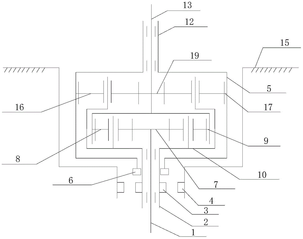
[0037] Such as figure 1 As shown, the clutch device described in this embodiment includes a dehydration pin 6 installed on the lower end of the brake wheel 5, a clutch sleeve 3 installed on the input shaft sleeve 2 and rotating integrally with the input shaft sleeve, and a braking pin installed on the lower end of the housing 15. Pin 4 and driving clutch sleeve 3 are respectively connected to / disconnected with dehydration pin 6 and brake pin 4;
[0038] In the washing state, the drive unit controls the clutch sleeve 3 to be connected to the brake pin 4 and disconnected from the dehydration pin 6 . In the dehydration state, the drive unit controls the clutch sleeve 3 to be connected to the dehydration pin 6 and to be disconnected from the brake pin 4 .
Embodiment 2
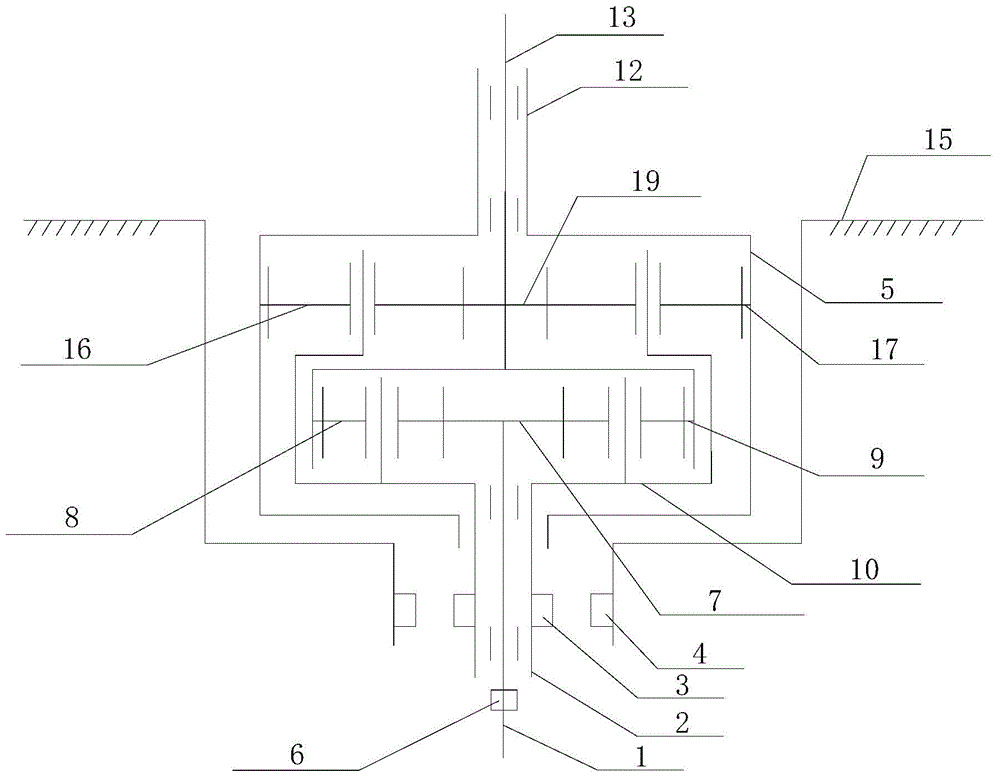
[0040] Such as figure 2 As shown, the clutch device described in this embodiment includes a dehydration pin 6 installed on the input shaft 1, a clutch sleeve 3 installed on the input shaft sleeve 2 and rotating integrally with the input shaft sleeve, and a brake pin 4 installed at the lower end of the housing 15. And the drive unit that drives the clutch sleeve 3 to connect / disconnect with the dehydration pin 6 and the brake pin 4 respectively;
[0041] In the washing state, the drive unit controls the clutch sleeve 3 to be connected to the brake pin 4 and disconnected from the dehydration pin 6 . In the dehydration state, the drive unit controls the clutch sleeve 3 to be connected to the dehydration pin 6 and to be disconnected from the brake pin 4 .
Embodiment 3
[0043] In the above embodiment, the clutch sleeve 3 is slidably installed on the input shaft sleeve 2 up and down, and can rotate integrally with the input shaft sleeve; the clutch sleeve 3 is controlled by the drive unit to slide up and down to be splined with the dehydration pin 6 and the brake pin 4, When disconnected, the drive unit includes a return spring and a device to drive the action of the clutch sleeve. The device is electromagnetically driven or mechanically driven, such as an electromagnetic clutch coil or a shift fork structure.
PUM
 Abstract
Description
Claims
Application Information