

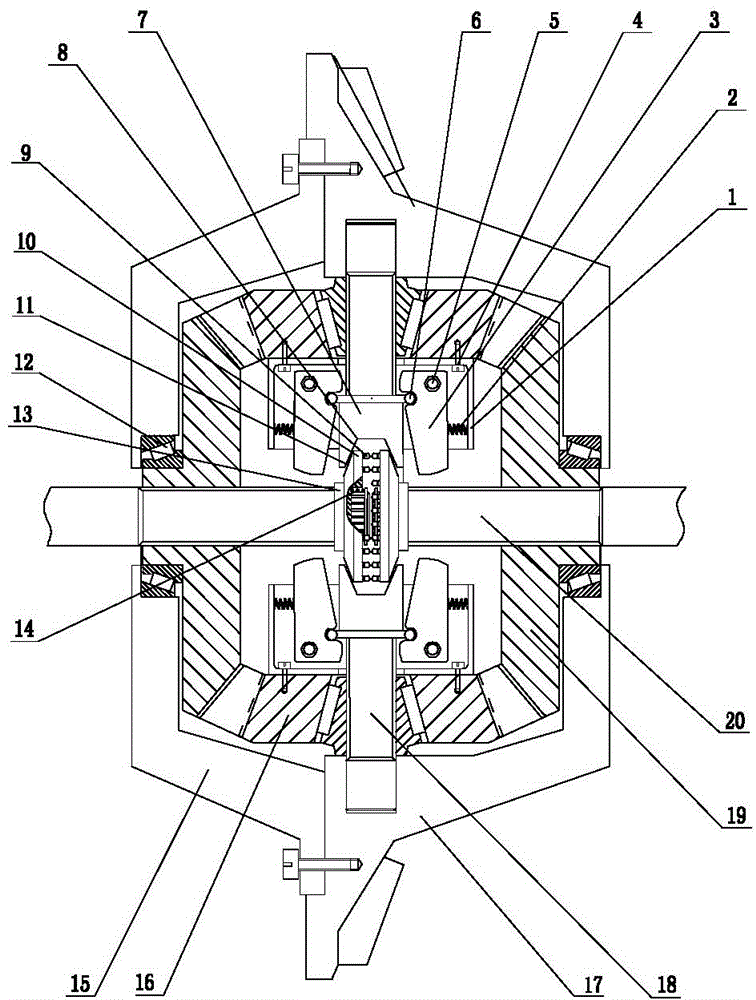
Centrifugal speed limiting differential mechanism
A differential, centrifugal technology, applied in the direction of differential transmission, belt/chain/gear, mechanical equipment, etc., can solve the problem of small power output torque slip, improve power output and limit locking torque slip Proportional, functionally reliable, avoid damaging impact effects
- Summary
- Abstract
- Description
- Claims
- Application Information
AI Technical Summary
Problems solved by technology
Method used
Image

Examples
Embodiment
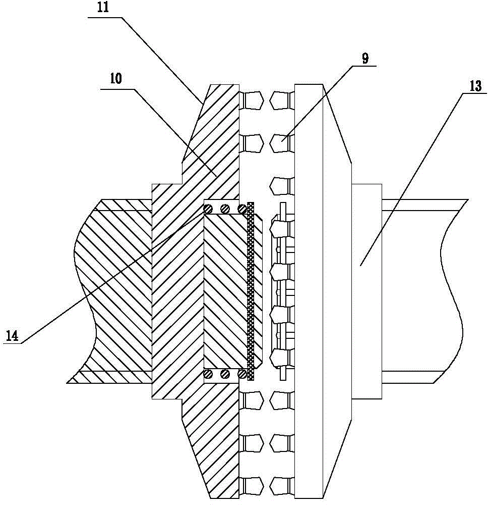
[0017] Example: such as Figure 1 ~ Figure 2 As shown, the present invention includes an outer casing formed by covering the front casing 15 and the rear casing 17, a planetary gear shaft 18, two half-shaft bevel gears 19, two planetary gears 16 and two spline half-shafts 20, two A half-shaft bevel gear 19 is supported and installed in the inner cavity of the housing through bearings 12, and two splined half-shafts 20 are mounted on the left and right ends of the half-shaft bevel gear 19 respectively, and the planetary gear 16 and the half-shaft bevel gear 19 cooperate with each other; The planetary gear shaft 18 is divided into two sections. The two-section planetary gear shaft 18 is respectively supported and installed on the upper and lower ends of the planetary gear 16 through tapered roller bearings and extended to be placed in the inner cavity wall of the housing. The two sections of the planetary gear shaft 18 are close to each other. The ends are respectively provided ...
PUM
 Abstract
Description
Claims
Application Information