
Super-large field-of-view fish eye lens

A field of view fish and eye lens technology, applied in the field of optical wide-angle lens and optical lens, can solve the problems of poor imaging quality, large number of lenses, complex optical system, etc.

Inactive Publication Date: 2015-07-22
SHANGHAI UNIV
View PDF4 Cites 13 Cited by
  • Summary
  • Abstract
  • Description
  • Claims
  • Application Information

AI Technical Summary

Problems solved by technology

Some early design ideas of fisheye lenses are very simple, and cannot well compensate the aberrations produced by the optical system, so the image quality is not very good
With the gradual improvement of the theory in the later stage, a high-quality imaging system can be obtained through the compensation calculation of aberrations and the optimization function of optical software. However, the obtained optical system is generally more complicated, and the number of lenses is relatively large, which greatly increases the Difficulty in manufacturing technology and precision, and previous theories have certain limitations in the design of fisheye lenses

Method used

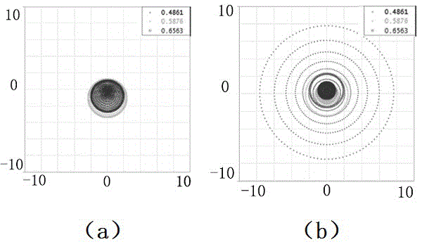
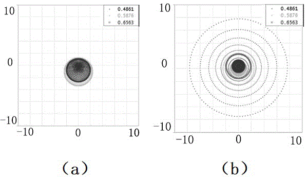

Image

  • Super-large field-of-view fish eye lens
  • Super-large field-of-view fish eye lens
  • Super-large field-of-view fish eye lens

Examples


Embodiment 1

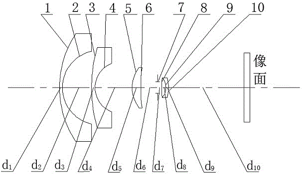
[0038] In this example, see Figure 1-8 and Figure 10, a super large field of view fisheye lens, characterized in that the optical system is a structure of 5 elements in 4 groups, arranged from left to right along the common central axis of the lenses, and the composition of the lenses is: the first group with negative diopter The lens and the second group of lenses with positive diopter, the first group of lenses are composed of the first negative lens and the second negative lens arranged in sequence from the left object side to the right image side, the second group of lenses is composed of the first negative lens Three positive lenses, the fourth positive lens and the fifth negative lens are composed of three lenses arranged in sequence from left to right. The mirror surface facing the object plane of the fifth negative lens is the first front mirror surface 1, the second front mirror surface 3, the third front mirror surface 5, the fourth front mirror surface 8 and the ...

Embodiment 2

[0054] This embodiment is basically the same as Embodiment 1, the difference is:

[0055] In this example, see Figure 1-9 And following table 2, the aspheric coefficient of the first front mirror surface 1 towards the first negative lens of the object plane is-0.44, and the aspheric coefficient of the second front mirror surface 3 of the second negative lens towards the object plane is- 0.89, the first rear mirror surface 2 of the first negative lens facing the image plane, the second rear mirror surface 4 of the second negative lens facing the image plane, and the mirror surfaces of other lenses are all spherical. The overall structural parameters of the super large field of view fisheye lens optical system are set as follows:

[0056] The total focal length of the optical system is: EFL=14.64;

[0057] Total length of optical system: L=96.40;

[0058] Full field of view: 0°≤2ω≤180°;

[0059] Dominant wavelength: 0.58756;

[0060] Back focal length: l F =36.92;

[006...


PUM

PropertyMeasurementUnit
Full field of viewaaaaaaaaaa

Abstract

The invention discloses a super-large field-of-view fish eye lens. An optical system is of a four-set five-piece structure, the super-large field-of-view fish eye lens is composed of a first lens set with negative diopter and a second lens set with positive diopter from left to right, the first lens set is composed of a first negative lens and a second negative lens sequentially from object space to image space, the second lens set is composed of a third positive lens, a fourth positive lens and a fifth negative lens, each of the fourth positive lens and the fifth positive lens is a balsaming lens, and a diaphragm is positioned between the third positive lens and the fourth positive lens. Parameters of the first lens set are acquired through an optimization method, and aberration of the second lens set is ensured to equally offset aberration caused by the first lens set. The optical system has the advantages of simple structure and good imaging quality.

Description

technical field [0001] The invention relates to an optical lens, in particular to an optical wide-angle lens, which is applied in the technical field of optical imaging and image acquisition equipment. Background technique [0002] The fisheye lens system refers to an optical system with a field of view of 180° or even larger. It was first proposed in 1932. Some early design ideas of fisheye lenses are very simple, and cannot well compensate the aberrations produced by the optical system, so the image quality is not very good. With the gradual improvement of the theory in the later period, a high-quality imaging system can be obtained through the compensation calculation of aberrations and the optimization function of optical software. However, the obtained optical system is generally more complicated, and the number of lenses is relatively large, which greatly increases the cost. The difficulty of manufacturing technology and precision, and the previous theories have certa...

Claims


Application Information

Patent Timeline
IPC IPC(8): G02B13/18G02B13/06
CPCG02B13/0045G02B13/006G02B13/06G02B13/18
Inventor 吕丽军田林牛智全方翔侍业
Owner SHANGHAI UNIV
Learn More