Precise controllable linear drive device and its combination

A linear drive and drive device technology, applied in the field of drives, can solve the problems of inability to meet the needs of micro-precision drive control and positioning, no instructions or reports are found, and low displacement control accuracy. Simple line effect

Active Publication Date: 2017-11-14
SHANGHAI JIAOTONG UNIV
View PDF10 Cites 0 Cited by
  • Summary
  • Abstract
  • Description
  • Claims
  • Application Information

AI Technical Summary

Problems solved by technology

[0003] The existing linear controllable drive devices mainly include linear motors. This kind of mechanism itself has a relatively complicated structure and low precision of displacement control. In particular, in the case of limited volume, it is often unable to provide a large driving force and cannot satisfy Modern industry's demand for micro precision drive control and positioning
[0004] At present, there is no description or report of the similar technology of the present invention, and no similar data at home and abroad have been collected yet.

Method used


Image

  • Precise controllable linear drive device and its combination
  • Precise controllable linear drive device and its combination
  • Precise controllable linear drive device and its combination

Examples


Embodiment 1

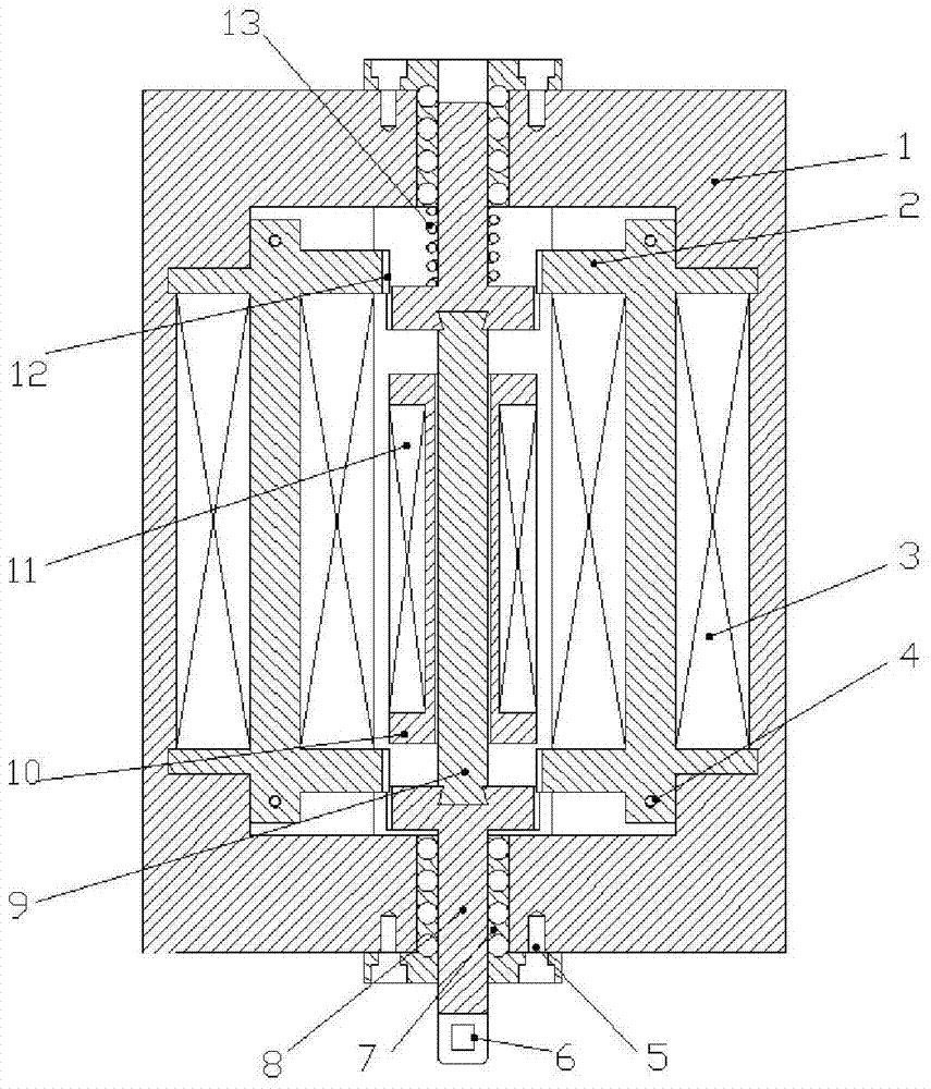
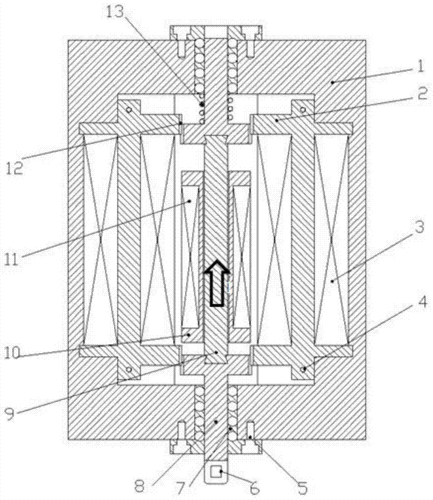
[0046] This embodiment provides a precision controllable linear drive device, including a base 1, mover parts (including mover outer end part 8 and mover middle end part 9) and several driving bodies (including magnetizer 2 and electromagnetic coil 3), the mover component is a magnetically conductive material, and the base 1 is provided with a first cavity for relative movement of the mover component and a second cavity for placing several driving bodies, and the mover component includes The outer part of the mover 8 and the middle part of the mover 9, wherein the outer part of the mover and the middle part of the mover are rigidly connected in a detachable manner, and the electromagnetic coil 3 and the magnetizer 2 are connected to the mover part. A magnetic circuit structure that interacts with each other is formed.

[0047] Preferably, the detachable manner is realized through a dovetail groove structure.

[0048] Further, one or more of the following components are also i...

Embodiment 2

[0060] This embodiment is a modification example of Embodiment 1. In this embodiment, an integrated structure is adopted between the outer end part of the mover and the middle end part of the mover.

Embodiment 3

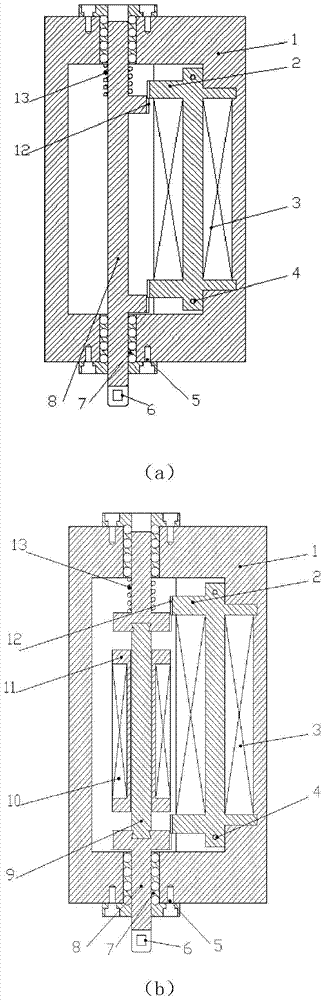
[0062] This embodiment is a modification example of Embodiment 1. In this embodiment, the outer end part 8 and / or the middle end part 9 of the mover are made of permanent magnet material, and the base 1 is provided with The first cavity that moves relative to the mover and the second cavity for placing several driving bodies (including the magnetizer 2 and the electromagnetic coil 3), the mover parts include the mover outer end part 8 and the mover middle end Part 9, wherein the outer end part of the mover is connected to the guide device, the electromagnetic coil 3 of the driving body, the electromagnetic coil 11 of the excitation part, and the magnetizer 2 form a magnetic circuit structure interacting with the mover part.

[0063] Further, as the permanent magnet material of the outer end part 8 of the mover and / or the middle end part of the mover, its magnetic pole direction is Figure 5 in the vertical direction.

[0064] The precision controllable driving device provided...


PUM


Abstract

The invention provides a precision controllable linear driver comprising a base, a mover part and at least one drive member. The base is provided with a first cavity allowing relative movement of the mover part and a second cavity used for holding the drive members. The mover part comprises two outer end parts and a middle part; the outer end parts are detachably and rigidly connected with or integrated to the middle part; the mover part is made of permeability magnetic material; magnetic circuit structures in mutual action are formed between the drive members and the mover part. The invention further provides a combined precision controllable linear driver based on the precision controllable linear driver. The precision controllable linear driver and its combination are simple in structure and light in weight and meet the need of the modern industry for precision control drive equipment.

Description

technical field [0001] The invention relates to an active vibration control and force-controlled displacement device in the technical field of drives, in particular to a precision controllable linear drive device and a combination thereof. Background technique [0002] The precision controllable driving device is mainly used in the active control of vibration, in the device that bears a certain load driving force and has positioning requirements, and provides a certain driving force by controlling the movement of the mover components to achieve active control of vibration and realize positioning control. [0003] The existing linear controllable drive devices mainly include linear motors. This kind of mechanism itself has a relatively complicated structure and low displacement control accuracy. In particular, it is often unable to provide a large driving force and meet the requirements of the limited volume. Modern industry demands for miniature precision drive control and p...

Claims


Application Information

Patent Timeline
Patent Type & Authority Patents(China)
IPC IPC(8): G05B19/19
CPCG05B19/19G05D19/02
Inventor 杨斌堂何泉
Owner SHANGHAI JIAOTONG UNIV
Why Eureka
Try Eureka