

Semiconductor integrated circuit and method for operating same
A technology of integrated circuits and semiconductors, applied in electrical components, adjusting electrical variables, instruments, etc., can solve the problems of the performance degradation of the stabilized power supply circuit and the difficulty in realizing the stabilized power supply, and achieve the effect of reducing the increase
- Summary
- Abstract
- Description
- Claims
- Application Information
AI Technical Summary
Problems solved by technology
Method used
Image

Examples
Embodiment approach 1
[0129] "Structure of Electronic Device Utilizing Stabilized Power Supply Circuit"
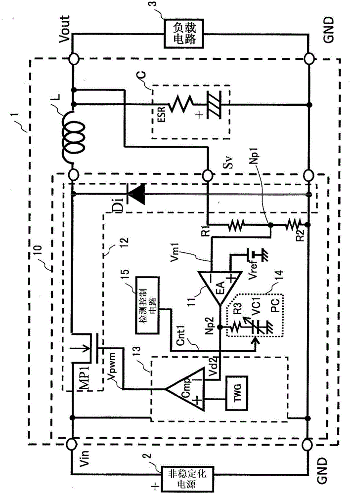
[0130] figure 1 It is a diagram showing the structure of an electronic device using a stabilized power supply circuit 1 using the semiconductor integrated circuit 10 of the first embodiment.
[0131] The electronic device is composed of an unstabilized power supply 2, a stabilized power supply circuit 1, and a load circuit 3. The output voltage (Vin) of the unstabilized power supply 2 can be set to a voltage outside the recommended operating power supply range of the load circuit 3. The high-voltage side terminal (+) of the unstabilized power supply 2 is connected to the input terminal Vin of the stabilized power supply circuit 1, and the low-voltage side terminal (-) of the unstabilized power supply 2 is connected to the ground voltage GND. The stabilized power supply circuit 1 is configured to supply the load circuit 3 with an output voltage Vout generated by converting the input voltage Vin int...
Embodiment approach 2
[0300] Figure 23 It is a diagram showing the structure of an electronic device using a stabilized power supply circuit 1 using the semiconductor integrated circuit 10 of the second embodiment.
[0301] Figure 23 The stabilized power supply circuit 1 using the semiconductor integrated circuit 10 of the second embodiment shown and figure 1 The illustrated stabilization power supply circuit 1 using the semiconductor integrated circuit 10 of the first embodiment is different in that: Figure 23 The stabilized power supply circuit 1 using the semiconductor integrated circuit 10 of the second embodiment is a boost-type stabilized power supply circuit.
[0302] First of all, the first difference is as follows.
[0303] because Figure 23 The stabilized power supply circuit 1 using the semiconductor integrated circuit 10 of the second embodiment operates as a boost-type stabilized power supply circuit. During the on period T ON The smoothing coil L storing magnetic energy is connected betw...
Embodiment approach 3
[0316] Figure 24 It is a diagram showing the structure of an electronic device using a stabilized power supply circuit 1 using the semiconductor integrated circuit 10 of the third embodiment.
[0317] Figure 24 The stabilized power supply circuit 1 using the semiconductor integrated circuit 10 of the third embodiment shown and figure 1 The illustrated stabilization power supply circuit 1 using the semiconductor integrated circuit 10 of the first embodiment is different in that: Figure 24 The stabilized power supply circuit 1 using the semiconductor integrated circuit 10 of the third embodiment is a stabilized power supply circuit of a series regulator type.
[0318] That is, in order to Figure 24 The stabilized power supply circuit 1 using the semiconductor integrated circuit 10 of the third embodiment operates as a series regulator-type stabilized power supply circuit, and passes the error amplifier 11 so that the output voltage Vout becomes constant even if the input voltage V...
PUM
 Abstract
Description
Claims
Application Information