Polymer coating diaphragm used for lithium ion battery

A polymer coating and lithium-ion battery technology, which is applied to battery pack components, separators/films/diaphragms/spacers, circuits, etc., can solve the problems of weak battery hardness, poor viscosity, and large resistance increase , to achieve the effect of reducing the increase of the air permeability value, increasing the conductivity, and reducing the increase

Pending Publication Date: 2019-02-01
SHANGHAI DINHO NEW MATERIAL TECH CO LTD
View PDF4 Cites 6 Cited by
  • Summary
  • Abstract
  • Description
  • Claims
  • Application Information

AI Technical Summary

Problems solved by technology

[0008] In order to overcome the polymer separator for lithium-ion batteries in the prior art, the coating film with uniform distribution of the coating will cause a large increase in resistance with the increase of coating thickness, and the viscosity performance of the pole piece after hot pressing is relatively poor; and The hardness of the battery after assembly of the coating film with large dot distribution is relatively weak, and the technical problem of lithium precipitation phenomenon will occur at the larger dots. Polymer Separator for Lithium-ion Batteries with Dot Distribution

Method used


Image

  • Polymer coating diaphragm used for lithium ion battery
  • Polymer coating diaphragm used for lithium ion battery
  • Polymer coating diaphragm used for lithium ion battery

Examples


Embodiment 1

[0044] In this example, anilox roller coating is used to prepare the polymer-coated separator for lithium-ion batteries of the present invention.

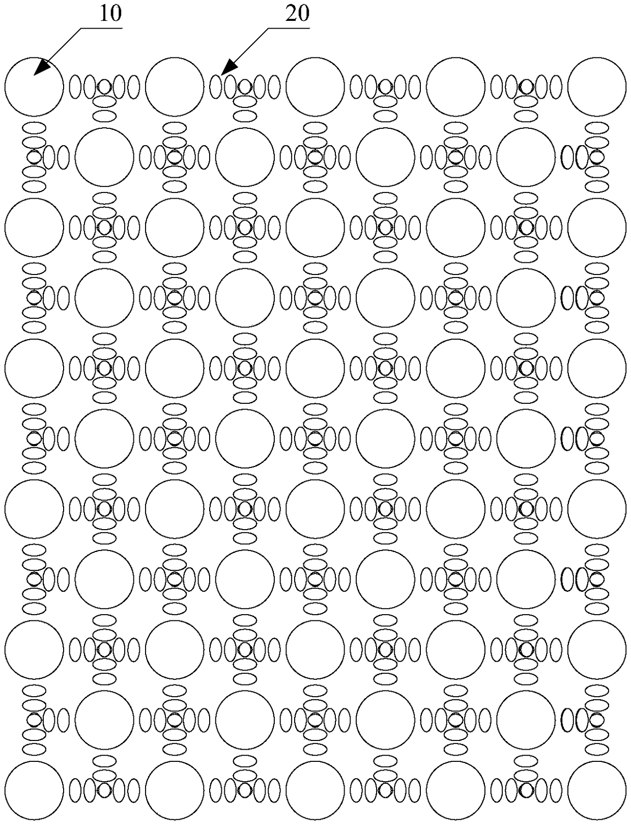
[0045] The preparation of consistent polymer slurry is achieved by a dot-shaped anilox roller designed with regular size engraving points, where the surface of the anilox roller is set with notches of large and small pits at specific positions, and the interval between the notches is 100- 800 microns, pattern as figure 1 As shown, using the printing principle, the polymer paste is coated on the base film.

[0046] Such as figure 1 As shown in the schematic diagram, using the pattern of the anilox roller, under the action of coating pressure, the polymer is distributed in the way of concave points 10 and small points 20 on the anilox roller, and finally the diaphragm base film is distributed into corresponding The structure of a polymer with bumps and dots at intervals.

[0047] Preparation of water-based polymer slurry: Mix and ...

Embodiment 2

[0055] In this embodiment, the slurry with non-uniform size and particle size is used to prepare the polymer-coated separator for lithium-ion batteries of the present invention.

[0056] Polymers with double peaks in particle size distribution are used, and the peak distributions are located at 5-10 microns and 0.1-1 microns respectively. The slurry is prepared, transferred to the substrate by micro-gravure coating, and distributed on both sides of the film.

[0057] Preparation of water-based polymer slurry: Mix and stir 78 parts of deionized water and 12 parts of polyvinylidene fluoride evenly, then add 10 parts of CMC and mix and stir evenly to obtain a stable and uniform water-based mixed slurry; the particle size distribution of the obtained slurry is The range is controlled at D50<20um.

[0058] Coating: The aqueous mixed slurry prepared in step 1 is coated on both sides of a PP film with a thickness of 20um by micro-gravure coating to form a polymer coating, which is dr...


PUM

PropertyMeasurementUnit
thicknessaaaaaaaaaa
diameteraaaaaaaaaa
diameteraaaaaaaaaa

Abstract

The invention provides a polymer coating diaphragm used for a lithium ion battery. The diaphragm includes a base film and a polymer distributed thereon in the manner of protruding points distributed at intervals and some scattered small dots. The size of the protruding points on the polymer coating diaphragm is about dozens of microns, which approximates to the granularity of the cathode and anode, so that the lithium ion battery is basically free of lithium separation phenomenon; in addition, there are some scattered small dots around the protruding points, so that after hot pressing, an electrolyte is easy to absorb to achieve a certain swelling effect; therefore, the content of free-state electrolyte is low and the battery is good in security.

Description

technical field [0001] The invention relates to the field of chemical batteries, in particular to the field of coated diaphragms used in lithium ion batteries. Background technique [0002] Lithium-ion batteries are generally batteries that use lithium alloy metal oxides as positive electrode materials, graphite as negative electrode materials, and non-aqueous electrolytes. The charging and discharging process of lithium-ion batteries is the intercalation and deintercalation process of lithium ions. During the intercalation and deintercalation process of lithium ions, it is accompanied by the intercalation and deintercalation of electrons equivalent to lithium ions (the positive electrode is customarily represented by intercalation or deintercalation, while the negative electrode is represented by insertion or deintercalation). During the charge and discharge process, lithium ions intercalate / deintercalate and intercalate / deintercalate back and forth between the positive an...

Claims


Application Information

Patent Timeline
Patent Type & Authority Applications(China)
IPC IPC(8): H01M2/18H01M2/16H01M2/14H01M50/403H01M50/414H01M50/417H01M50/426H01M50/449H01M50/457H01M50/463H01M50/489
CPCH01M50/403H01M50/411H01M50/463Y02E60/10
Inventor 李建华程素贞杨劲帆潘彪黎广军
Owner SHANGHAI DINHO NEW MATERIAL TECH CO LTD
Why Eureka
Try Eureka