Position detecting device, position detecting system, and controlling method of position detecting device

A detection device and a technology for detecting light, which are applied in the direction of measuring devices, optical devices, and data processing input/output processes, can solve problems such as the undeniable impact of calibration execution, and achieve good efficiency, simplified structure, and control. simplified effect

Active Publication Date: 2015-07-22
SEIKO EPSON CORP
View PDF5 Cites 2 Cited by
  • Summary
  • Abstract
  • Description
  • Claims
  • Application Information

AI Technical Summary

Problems solved by technology

[0004] However, when a plurality of devices with different methods of detecting the operating position are used in com

Method used


Image

  • Position detecting device, position detecting system, and controlling method of position detecting device
  • Position detecting device, position detecting system, and controlling method of position detecting device
  • Position detecting device, position detecting system, and controlling method of position detecting device

Examples


Example Embodiment

[0037] Hereinafter, embodiments of the present invention will be described with reference to the drawings.
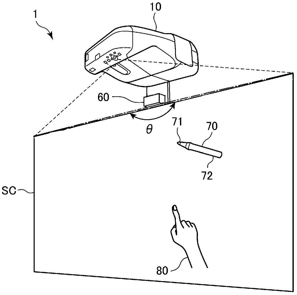
[0038] figure 1 It is a diagram showing the configuration of the projection system 1 to which the embodiment of the present invention is applied. The projection system 1 includes a projector 10 installed above the screen SC (projection surface, operation surface), and a light emitting device 60 (light emitting section) installed above the screen SC.

[0039] The projector 10 is installed directly above or diagonally above the screen SC, and projects an image to the screen SC diagonally below. In addition, the screen SC exemplified in this embodiment is a flat panel or a screen fixed on a wall surface or erected on a floor surface. The present invention is not limited to this example, and a wall surface may be used as the screen SC. In this case, the projector 10 and the light emitting device 60 may be installed on the upper part of the wall surface used as the screen SC.

...


PUM


Abstract

A projector includes a light output device outputting detection light on a screen, a position detection unit detecting an indication position, and a calibration control unit. The position detection unit performs a first detecting operation detecting an indication position by using the detection light, and a second detecting operation detecting an indication position by using light other than the detection light. The calibration control unit executes calibration associating a position detected in the second detecting operation with a position on the screen, and restricts output of the detection light while the calibration is executed.

Description

technical field [0001] The invention relates to a position detection device, a position detection system and a control method of the position detection device. Background technique [0002] Conventionally, among devices that detect an operation position when an input operation is performed, a device that performs calibration in order to accurately detect the operated position is known (for example, refer to Patent Document 1). The device described in Patent Document 1 performs automatic calibration by capturing an image displayed on the operation surface. In addition, it is also possible to allow the user to perform an operation to designate a predetermined point on the operation surface, and to detect the operation position for calibration. [0003] Patent Document 1: Japanese Patent Laid-Open No. 2011-227600 [0004] However, when a plurality of devices having different methods of detecting the operating position are used in combination, the possibility that the differen...

Claims


Application Information

Patent Timeline
IPC IPC(8): G06F3/042G06F3/038
CPCG01B11/14G06F3/03545G06F3/0418G06F3/0425
Inventor 田村明彦
Owner SEIKO EPSON CORP
Why Eureka
Try Eureka