A built-in oil-immersed transformer nitrogen injection device

An oil-immersed transformer, built-in technology, used in transformer/inductor parts, electrical components, fire rescue and other directions, can solve the problems of hidden fire accidents, long distance from the fault point, increased oil pressure, etc., and achieve the effect of nitrogen injection Good, easy installation, cost reduction effect

Active Publication Date: 2017-02-01
ELECTRIC POWER RES INST OF GUANGXI POWER GRID CO LTD
View PDF5 Cites 0 Cited by
  • Summary
  • Abstract
  • Description
  • Claims
  • Application Information

AI Technical Summary

Problems solved by technology

Oil-immersed transformers are the most commonly used, but due to their own structure, insulating materials used and operating conditions of transformers, oil-immersed transformers have hidden dangers of fire accidents
Transformer explosion and fire is usually caused by arc discharge caused by transformer winding insulation damage, which leads to a sudden increase in oil temperature. Cracking, air mixed with flammable gas will explode, causing transformer oil to burn, main transformer to catch fire, substation power outage, causing huge losses to the power grid, and at the same time causing extremely bad impact on society
[0003] At present, the transformer fire protection system based on the principle of oil discharge and nitrogen injection at home and abroad adopts the external nitrogen injection method, that is, the bottom of the transformer oil tank is perforated, and then connected to the external nitrogen injection pipeline, and nitrogen is injected into the oil tank from the hole on the wall of the oil tank. , the processing time is long in this way, the distance from the fault point is far away, the effect of nitrogen injection is poor, there are many leakage points, maintenance is difficult, and the cost is high

Method used


Image

  • A built-in oil-immersed transformer nitrogen injection device
  • A built-in oil-immersed transformer nitrogen injection device
  • A built-in oil-immersed transformer nitrogen injection device

Examples


Embodiment 1

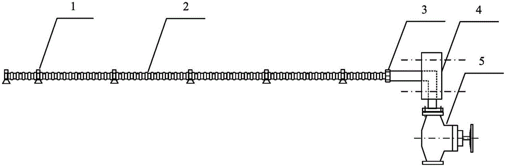
[0020] Such as figure 1 , Figure 5 As shown, a built-in oil-immersed transformer nitrogen injection device includes: a nitrogen inlet pipe, a fixing device for the nitrogen inlet pipe, a connecting flange 4 and a stop valve 5 . The nitrogen inlet pipe adopts perforated corrugated pipe 2, and the fixing device of nitrogen inlet pipe adopts permanent magnet 1. The perforated corrugated pipe 2 is arranged at the bottom of the transformer oil tank 8 and fixed by permanent magnet 1. The hole on the perforated corrugated pipe 2 faces the transformer The winding 10 and one end of the perforated bellows 2 are connected to the connecting flange 4 through the connecting nut 3 .

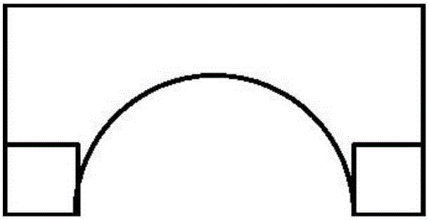
[0021] Such as Figure 4 , Figure 5 As shown, the connecting flange 4 is provided with a front and rear channel 11 and a middle channel 12, and the connecting flange 4 is installed between the oil discharge port 6 and the oil discharge valve 7 of the transformer oil tank through bolts, and the front and re...

Embodiment 2

[0025] This embodiment focuses on the differences from the previous embodiments, and the similarities will not be repeated. The difference between this embodiment and the previous embodiments is that the perforated bellows 2 can be arranged on the inner wall of the transformer oil tank 8, and the perforated bellows The holes on the 2 face the transformer winding 10, and are fixed by the permanent magnet 1. This example makes use of the flexible characteristics of bellows, which is suitable for transformer oil tank walls of various shapes such as round, square, and hexagonal, and the nitrogen injection hole is close to the middle of the winding, which is prone to failure, and has the advantages of short nitrogen injection distance and fast cooling speed. Fast, timely, effective and other advantages.

Embodiment 3

[0027] This embodiment focuses on the differences from the previous embodiments, and the similarities will not be repeated. The difference between this embodiment and the previous embodiments is that multiple perforated corrugated pipes 2 can be arranged on the bottom or four walls of the transformer oil tank 8 On the top, preferably, there are 2 on the bottom and 2 on the four walls, and they are connected to the connecting flange 4 through a five-way joint. This example improves the speed of nitrogen injection, and has the advantages of fast cooling speed, wide range and good effect.

[0028] The middle channel 12 of the connecting flange 4 in the above embodiments can be used as an oil intake port and an oil chromatography monitoring port, and only a three-way connecting piece needs to be inserted between the connecting flange 4 and the shut-off valve 5 .

[0029] As the front-end device of the nitrogen injection system, the present invention can be connected with other aut...


PUM


Abstract

The invention provides a built-in nitrogen injection device of an oil-immersed transformer. The device comprises an open corrugated pipe, a permanent magnet, a connection nut, a connection flange and a stop valve, and is characterized in that the nitrogen injection device of the oil-immersed transformer is quick to install, an oil tank structure does not need to be changed, and leaking points are few. The open corrugated pipe is fixed at the bottom or the inner wall of a transformer oil tank through the permanent magnet, one end of the open corrugated pipe is closed, the other end of the open corrugated pipe is connected to the connection flange through the connection nut, the connection flange is provided with a front channel, a rear channel and a middle channel, the front channel and the rear channel of the connection flange are connected with an oil discharge opening and an oil discharge valve of the transformer oil tank, and the middle channel of the connection flange is connected with a nitrogen inlet pipe and the stop valve. By means of the built-in nitrogen injection device, a nitrogen injection point can be aligned to a transformer winding at a short distance, coverage is comprehensive, the nitrogen injection effect is good, installing is convenient, a transformer box body does not need to be improved, and investment cost is reduced.

Description

technical field [0001] The invention relates to the field of electric fire protection, in particular to an oil-immersed transformer cooling and fire extinguishing component-a nitrogen injection device. Background technique [0002] Power transformers are one of the most important equipment in power plants and substations, and their safety has an important impact on power grids and social stability. Oil-immersed transformers are the most commonly used, but due to their own structure, insulating materials used and operating conditions of transformers, oil-immersed transformers have hidden dangers of fire accidents. Transformer explosion and fire is usually caused by arc discharge caused by transformer winding insulation damage, which leads to a sudden increase in oil temperature. Cracking, air and flammable gas mixed to explode, causing transformer oil to burn, main transformer to catch fire, substation power outage, causing huge losses to the power grid, and at the same time...

Claims


Application Information

Patent Timeline
Patent Type & Authority Patents(China)
IPC IPC(8): H01F27/00A62C3/16
Inventor 陈梁远黎大健赵坚张磊张玉波秦楷蒲金雨
Owner ELECTRIC POWER RES INST OF GUANGXI POWER GRID CO LTD
Why Eureka
Try Eureka