Cable laying and displacing frame

A technology of cables and cables, applied in cable laying equipment, optical fiber/cable installation, etc., can solve the problems of low work efficiency, labor consumption, poor construction effect, etc., and achieve the effect of convenient operation and simple structure

Inactive Publication Date: 2015-07-22
STATE GRID SHANDONG ELECTRIC POWER COMPANY WEIFANG POWER SUPPLY +1
View PDF6 Cites 19 Cited by
  • Summary
  • Abstract
  • Description
  • Claims
  • Application Information

AI Technical Summary

Problems solved by technology

The winding roller of a single thick cable is heavy, and it needs the cooperation of multiple people to lift the winding roller to the site first, and then roll the winding roller together to wind the cable off the winding roller, which is very difficult to operate. Difficult and labor intensive
Simultaneous laying of multiple cables also requires the cooperation of multiple people. During specific operations, each person needs to be responsible for the laying out of a reel of cables, and then a special person is responsible for merging the cables into a bundle. During the process of laying cables, some cables It is easy to bend and twist to cause cable damage. It can be seen that the laying method of multiple cables is also very difficult and the work efficiency is low and the construction effect is poor.

Method used


Image

  • Cable laying and displacing frame
  • Cable laying and displacing frame
  • Cable laying and displacing frame

Examples


Embodiment Construction

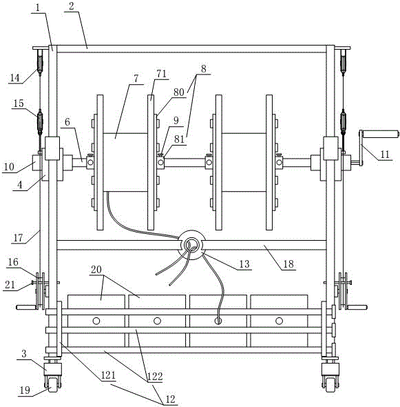
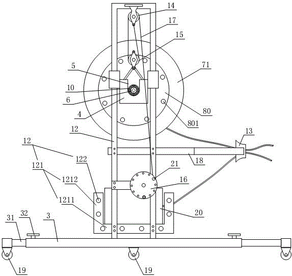
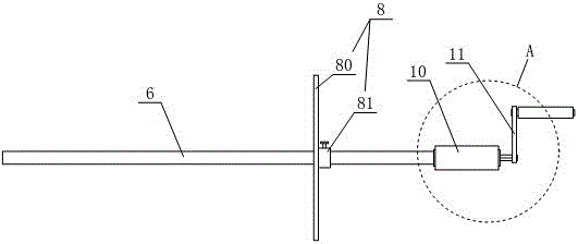
[0024] Referring to the accompanying drawings, the cable laying rack includes two brackets 1 arranged vertically and at intervals from left to right and a crossbeam 2 connected to the top of the two brackets 1. The bottom ends of the two brackets 1 are vertically fixed to each other and extend along the front and rear directions. A strip-shaped base 3, a support block 4 is vertically slidably installed on each of the two supports 1, and the two support blocks 4 are correspondingly arranged and are respectively driven and positioned by the handwheel driving mechanism arranged on the respective supports 1, the two support blocks 4 The top end is provided with a groove 5, a rotating shaft 6 is arranged between the two grooves 5, and at least two fixed wheel discs 8 that can be connected with the wire retaining discs 71 on both sides of the winding roller 7 are slidably sleeved on the rotating shaft 6 and The fixed wheel disc 8 can be positioned on the rotating shaft 6 through the ...


PUM


Abstract

The invention relates to a cable laying and displacing frame. The cable laying and displacing frame comprises two brackets and a cross beam, wherein the cross beam is connected to the top ends of the two brackets; a strip-shaped base is vertically and fixedly connected to the bottom of each of the two brackets, and a supporting block is vertically and slidably mounted on each of the two brackets; the two supporting blocks are correspondingly arranged and are respectively driven and positioned by virtue of hand wheel driving mechanisms which are respectively arranged on the two brackets, grooves are formed in the tops of the two supporting blocks, a rotating shaft is arranged between the two grooves and is slidably sleeved by at least two fixedly connected wheel discs which are connected with baffle wire discs on two sides of a wire winding roller; two ends of the rotating shaft are respectively rotatably sleeved by rotary sleeves, the two rotary sleeves are respectively arranged in the two grooves, and a manual shaking handle for driving the rotating shaft to rotate is mounted at the end part of the rotating shaft; a bottom trough is detachably mounted between the bottoms of the two brackets, and wire collection cylinders are detachably mounted above the bottom trough between the two brackets. The cable laying and displacing frame has the advantages that the structure is simple, the operation is convenient, the working efficiency is high, and a cable laying effect is good.

Description

technical field [0001] The invention relates to the field of cable laying construction, in particular to a cable laying rack. Background technique [0002] Cables are divided into cables for transmitting electrical signals and optical cables for transmitting optical signals. Cable laying refers to putting cables into cable channels or erecting them on poles and towers. The laying of the cable must take the cable. The cable is generally wound on the winding roller. Some cables (such as optical cables) are also stored in the box. cable out. [0003] The types and types of cables and the applications are different, so the laying methods and operation procedures are also different. There are two common laying methods: 1) single-deck thick cable laying construction; 2) multi-deck or multi-box cable laying construction at the same time. The winding roller of a single thick cable is heavy, and it needs the cooperation of multiple people to lift the winding roller to the site fir...

Claims


Application Information

Patent Timeline
IPC IPC(8): H02G1/06G02B6/54
Inventor 付明义马建生王建玲金志强刘刚徐亭亭谭虎孙秀云李文波丁峰李明明王小亮付小霞李传龙刘晓楠
Owner STATE GRID SHANDONG ELECTRIC POWER COMPANY WEIFANG POWER SUPPLY
Why Eureka
Try Eureka