
Method for configuring capacity of asynchronous wind power plant reactive power compensation device under grid fault

A technology for compensating equipment and power grid faults, applied in reactive power compensation, reactive power adjustment/elimination/compensation, circuit devices, etc., can solve problems that do not involve reactive power compensation equipment capacity allocation, etc., to improve low voltage ride-through capability , Improving the effect of feasibility and economy

Active Publication Date: 2015-07-22
CHONGQING UNIV
View PDF4 Cites 3 Cited by
  • Summary
  • Abstract
  • Description
  • Claims
  • Application Information

AI Technical Summary

Problems solved by technology

Although the above studies can provide a basis for determining the capacity allocation of reactive power compensation equipment during the steady-state operation of asynchronous wind farms, none of them involve the allocation of reactive power compensation equipment capacity during the transient operation of asynchronous wind farms.

Method used


Image

  • Method for configuring capacity of asynchronous wind power plant reactive power compensation device under grid fault
  • Method for configuring capacity of asynchronous wind power plant reactive power compensation device under grid fault
  • Method for configuring capacity of asynchronous wind power plant reactive power compensation device under grid fault

Examples


Embodiment Construction

[0027] The specific implementation of the present invention will be described in detail below in conjunction with calculation examples and drawings.

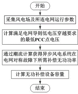
[0028] Combine figure 1 As shown in the calculation process, the specific implementation steps of the capacity configuration method for reactive power compensation equipment of asynchronous wind farms under grid failure are as follows:

[0029] (A) Collect the operating parameters of the wind farm and the connected grid:

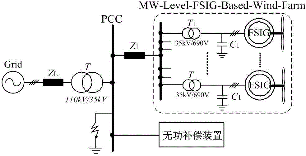
[0030] In this example, the wind farm is composed of 30 single fixed-speed asynchronous wind turbines with a rated power of 1MW in parallel. The system topology is as follows figure 2 Shown. The output voltage of the asynchronous motor is 0.69kV, which is connected to the internal power grid of the wind farm through a 0.69 / 35kV transformer. After being connected to a 35 / 110kV booster station through a 2km transmission line, it is connected to the local 110kV grid through a 100km transmission line, and reactive powe...


PUM


Abstract

The invention discloses a method for configuring capacity of an asynchronous wind power plant reactive power compensation device under a grid fault. The method comprises the following steps: (A) calculating minimum PCC point voltage of the asynchronous wind power plant capable of meeting the grid code low-voltage ride through requirement when the fault is restored; (B) calculating the capacity of the reactive power compensation device corresponding to the minimum PCC point voltage; the capacity of the asynchronous wind power plant reactive power compensation device is configured to be not less than the minimum capacity S<C>. By adopting the method, the minimum value of the capacity of the reactive power compensation device for the asynchronous wind power plant PCC point capable of meeting the grid code middle-low-voltage ride through requirement can be calculated, the method is applicable to the existing synchronization wind power plant reactive power compensation device capacity plan, reference can be provided for the configuration of the reactive power compensation device for the real asynchronous wind power plant, the feasibility and economical performance of the real asynchronous wind power plant low-through modification scheme can be effectively improved, and the low-voltage ride-through capacity of a wind power plant and the transient voltage stability of the regional grid containing the asynchronous wind power plant can be improved.

Description

Technical field [0001] The invention relates to the field of capacity configuration of reactive power compensation equipment for large-capacity asynchronous wind farms, and particularly relates to a method for configuring the capacity of reactive power compensation devices of asynchronous wind farms for low voltage ride-through requirements in power grid guidelines. Background technique [0002] The new guideline for grid connection of wind farms "GB / T 19963-2011 Technical Regulations for Wind Farm Access to Power System" proposes that "when the voltage at the grid connection point of a wind farm drops to 20% of the nominal voltage, the wind turbines in the wind farm shall be guaranteed not to Strict requirements of 625ms continuous operation offline. In view of the uncontrollability of traditional fixed-speed asynchronous wind turbines, scholars at home and abroad have proposed a low-voltage ride-through modification plan for installing reactive power compensation equipment at t...

Claims


Application Information

Patent Timeline
IPC IPC(8): H02J3/18
CPCH02J3/1892Y02E10/76Y02E40/30
Inventor 姚骏周特郭利莎曾欣
Owner CHONGQING UNIV
Learn More