RC (Resistance-capacitance) type rotor crowbar

A resistance-capacitance and rotor technology, applied in reactive power compensation, reactive power adjustment/elimination/compensation, single-net parallel feeding arrangement, etc., can solve problems such as low-voltage ride-through that cannot be completely solved, and improve low-voltage ride-through capability , to achieve the effect of fast compensation

Inactive Publication Date: 2013-05-01
LANZHOU UNIVERSITY OF TECHNOLOGY
View PDF4 Cites 0 Cited by
  • Summary
  • Abstract
  • Description
  • Claims
  • Application Information

AI Technical Summary

Problems solved by technology

Therefore, the application of SVC cannot completely solve the problem of low voltage ride through when the power grid fails

Method used


Image

  • RC (Resistance-capacitance) type rotor crowbar
  • RC (Resistance-capacitance) type rotor crowbar
  • RC (Resistance-capacitance) type rotor crowbar

Examples


Embodiment Construction

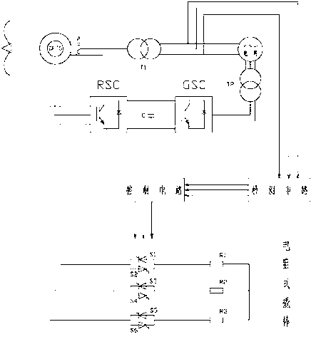
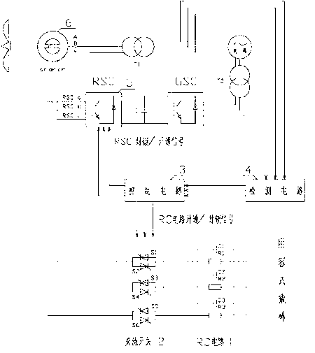
[0016] The structural diagram of the resistance-capacitance rotor crowbar applied to the DFIG system is as follows: figure 2 shown. The resistance-capacitance crowbar is composed of an RC circuit 1 , an AC switch 2 , a control circuit 3 and a detection circuit 4 . RC circuit 1 is a combined circuit of three sets of resistors and capacitors, each of which is a parallel connection of resistors and capacitors, respectively the first resistor R1 and the first capacitor C1, the second resistor R2 and the second capacitor C2, the third resistor R3 and Three groups of the third capacitor C3 form a three-phase combination form. One end of the resistance-capacitance rotor crowbar is connected to the rotor winding of DFIG 6 through the AC switch 2, and the other end is connected to each other to form a three-phase short circuit. The AC switch 2 is composed of three groups of anti-parallel thyristors, namely the first thyristor S1 and the second thyristor S2, the third thyristor S3 an...


PUM


Abstract

The invention discloses a RC (Resistance-capacitance) type rotor crowbar. The RC type rotor crowbar comprises an RC circuit 1, an alternating-current switch 2, a control circuit 3 and a detecting circuit 4, wherein one end of the RC circuit 1 is connected with the alternating-current switch 2; the other end of the RC circuit 1 is mutually connected to form a three-phase joint; the other end of the alternating-current switch is connected with a rotor winding of a DFIG6 (Doubly Fed Induction Generator 6); a turning-on / off control signal of the alternating-current switch is from the control circuit 3; the control circuit 3 is connected with the detecting circuit 4; the RC circuit 1 consists of three groups of resistors and capacitors; and the resistors and the capacitors in each group are connected in parallel.

Description

technical field [0001] The invention relates to the technical field of low-voltage ride-through of a doubly-fed wind power generation system, in particular to the rapid response and compensation of a doubly-fed wind power generation system to grid voltage drops. Background technique [0002] With the rapid development of wind power technology, the proportion of wind power in the power system is increasing. Doubly-fed induction generator (DFIG) is currently the main model used in wind farms. During the grid-connection process of this type of wind turbine, the stator winding of DFIG is directly connected to the grid. The failure of the grid directly affects the operation safety of the generator set. For example, common short-circuit faults on the grid side directly lead to a large drop in the voltage on the DFIG stator side, and generate overcurrent on the rotor side through electromagnetic coupling, which poses a serious threat to the safety of the machine-side converter. On...

Claims


Application Information

Patent Timeline
IPC IPC(8): H02J3/38H02J3/18
CPCY02E40/30
Inventor 王晓兰王惠中鲜龙
Owner LANZHOU UNIVERSITY OF TECHNOLOGY
Why Eureka
Try Eureka