
A hybrid direct current power transmission device and power transmission method for new energy grid connection

A hybrid direct current transmission and new energy technology, applied in the direction of power transmission AC network, single network parallel feeding arrangement, etc., can solve the problems of unsustainability, uncontrollable reactive power, grid impact, etc., and meet the requirements of transient performance , Improve low-voltage ride-through capability, high safety and reliability

Active Publication Date: 2017-10-31
CHINA ENERGY ENG GRP GUANGDONG ELECTRIC POWER DESIGN INST CO LTD
View PDF6 Cites 0 Cited by
  • Summary
  • Abstract
  • Description
  • Claims
  • Application Information

AI Technical Summary

Problems solved by technology

MMC-based flexible DC transmission technology has excellent wind power and photovoltaic power grid-connected controllability and strong anti-interference ability, and can effectively improve low-voltage ride-through capability to meet the transient performance requirements of grid-connected systems. The flexible DC power transmission generally needs to build flexible DC converter stations at both the sending end and the receiving end to carry out the transmission of DC power, resulting in complex control, large loss, and high cost
In the existing technology, new energy grid connection also adopts AC grid connection. Due to the unstable and unsustainable characteristics of new energy sources, the use of this grid connection method will cause a large impact on the power grid and affect the security of the power grid.
In addition, the conventional DC technology based on LCC (Line Commutated Converter, current source converter) is mature, with low loss and high reliability. shortcoming

Method used


Image

  • A hybrid direct current power transmission device and power transmission method for new energy grid connection
  • A hybrid direct current power transmission device and power transmission method for new energy grid connection
  • A hybrid direct current power transmission device and power transmission method for new energy grid connection

Examples


Embodiment 1

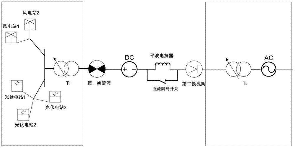
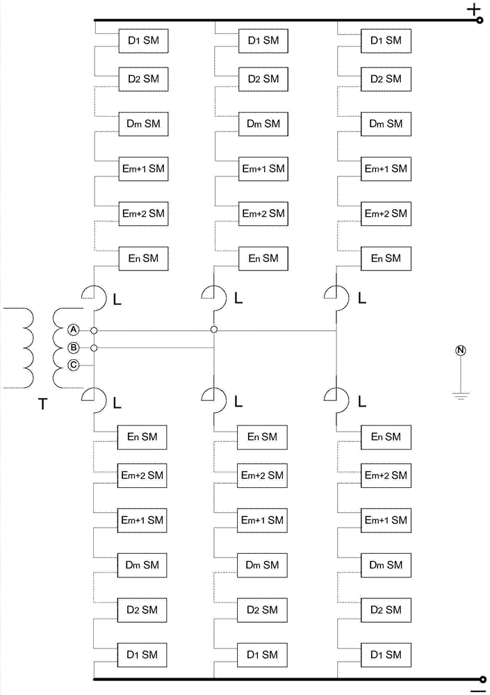
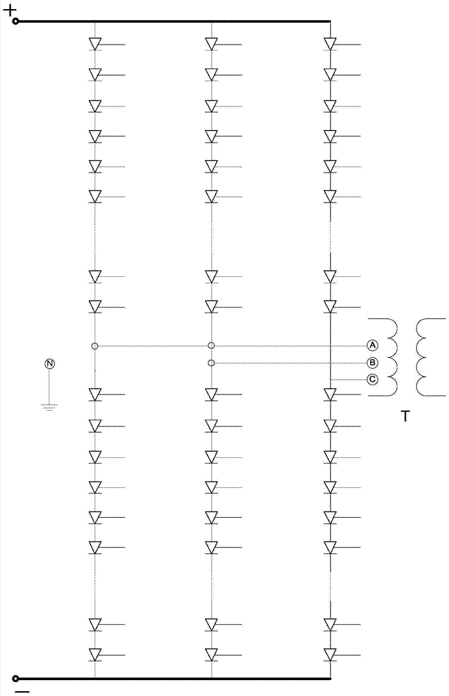
[0033] see figure 1 , this embodiment is a hybrid direct current transmission device for new energy grid connection, including: a first AC transformer, a first converter valve, a second converter valve, a second AC transformer, a smoothing reactor, and a DC isolation switch and an overhead direct current transmission line, wherein the first converter valve comprises a flexible direct current converter based on MMC, and the second converter valve comprises a conventional direct current converter based on LCC. The input end of the first AC transformer is connected to an external new energy generating device for converting the output voltage of the new energy generating device. The new energy generating device in this embodiment includes at least one wind power station and at least one photovoltaic power station.

[0034] Among them, the first AC transformer and the second AC transformer can generally adopt the method of on-load voltage regulation, and adjust the reference voltage ...


PUM


Abstract

The invention discloses a hybrid direct current power transmission device for new energy grid connection and a power transmission method thereof. A wave reactor, a DC isolation switch, a second converter valve, a second AC transformer and an AC grid; the first AC transformer is used to transform the output voltage of the new energy power generation device so that its secondary side voltage is the same as the first converter The valves are matched; the first converter valve includes a flexible DC converter based on MMC, which is composed of a D-type sub-module, an E-type sub-module and a reactor in series, which can self-clear DC fault current. The second converter valve comprises a conventional DC converter based on LCC, which consists of thyristor units connected in series. The secondary side of the second AC transformer is connected to the grid after matching the voltage of the AC grid. The invention integrates the dispersed new energy into the AC power grid, has little influence on the stability of the grid connection, and has low cost.

Description

technical field [0001] The invention belongs to the technical field of direct current power transmission in electric power systems, and in particular relates to a hybrid direct current power transmission device and a power transmission method for new energy grid connection. Background technique [0002] Energy is the engine of human development. With the continuous development of the global economy, the demand for energy is increasing day by day. The depletion of traditional fossil energy, the negative impact of hydropower resources on the environment, and the catastrophe of nuclear power accidents have all driven new energy to become the most sustainable development in the world. important subject. The most important new energy sources at present are wind power and solar power generation, but wind power and solar power are greatly affected by natural weather factors, and are random and intermittent in generation. , a huge test of stable operation, once the voltage quality ...

Claims


Application Information

Patent Timeline
Patent Type & Authority Patents(China)
IPC IPC(8): H02J3/38H02J3/36
CPCY02E60/60
Inventor 曾勇周敏王宏斌辛文成
Owner CHINA ENERGY ENG GRP GUANGDONG ELECTRIC POWER DESIGN INST CO LTD
Learn More