Network clock monitoring method and network clock monitoring device

A network clock and monitoring device technology, applied in the direction of synchronization devices, data exchange networks, digital transmission systems, etc., can solve problems such as degradation monitoring and early warning, lack of intelligent IT means, lack of clock looping or interlocking quality, and achieve Achieve self-monitoring, reduce network maintenance workload, and reduce the effect of failure probability

Active Publication Date: 2015-07-22
CHINA MOBILE GRP GUANGDONG CO LTD
View PDF5 Cites 5 Cited by
  • Summary
  • Abstract
  • Description
  • Claims
  • Application Information

AI Technical Summary

Problems solved by technology

[0014] The present invention provides a method and device for monitoring network clocks, which are used to solve the lack of monitoring and early warning methods for clock looping or interlocking quality degradation in the prior art. At the same time, the optimization of the clock network mainly depends on operation and maintenance personnel experience, lack of intelligent IT means

Method used


Image

  • Network clock monitoring method and network clock monitoring device
  • Network clock monitoring method and network clock monitoring device
  • Network clock monitoring method and network clock monitoring device

Examples


Embodiment 1

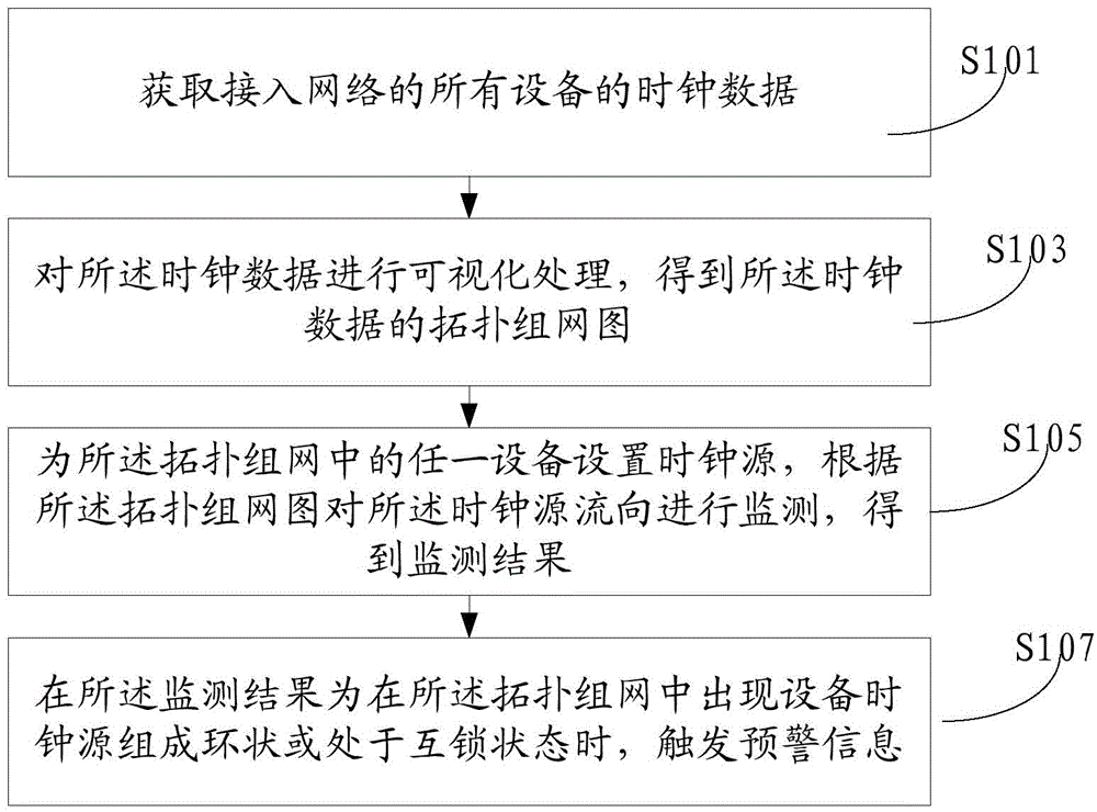
[0034] The monitoring methods of the network clock include:

[0035] S101: Obtain clock data of all devices connected to the network;

[0036] S103: Perform visual processing on the clock data to obtain a topology networking diagram of the clock data;

[0037] S105: Set a clock source for any device in the topological networking, monitor the flow of the clock source according to the topological networking diagram, and obtain a monitoring result;

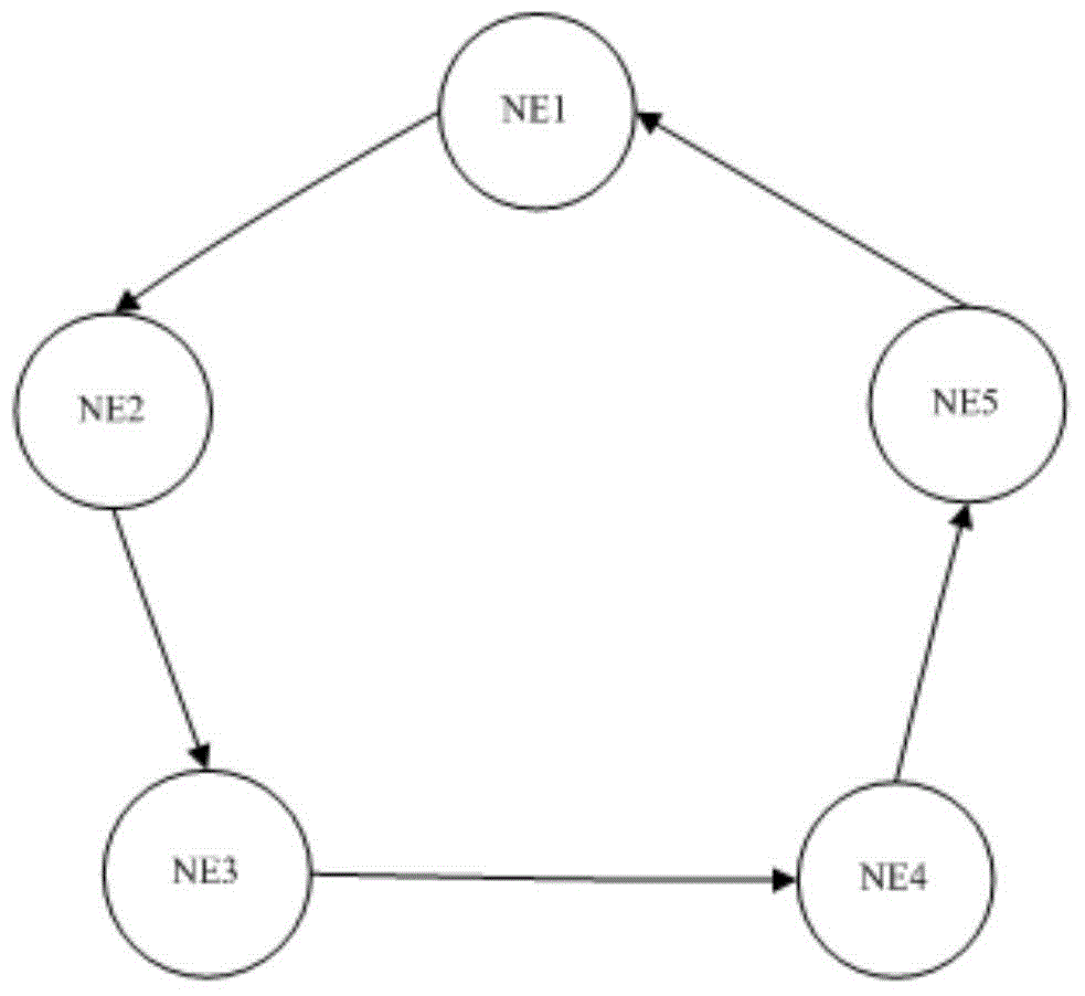
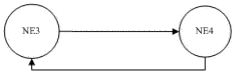
[0038] S107: When the monitoring result is that the device clock sources form a ring or are in an interlocked state in the topological networking, trigger warning information.

[0039]In the above technical solution of the present embodiment, in step S101, the clock data of all devices connected to the network are obtained, and the clock data of all devices connected to the network are collected according to the characteristics of the PTN network and the DLL interface provided by the device manufacturer. The clock data may include ...

Embodiment 2

[0043] Figure 4 A flow chart showing the method for monitoring a network clock according to Embodiment 2 of the present invention.

[0044] see Figure 4 As shown, the monitoring method of the network clock may include the following steps:

[0045] Step 401: Obtain all devices in the entire network;

[0046] Obtain all devices on the entire network, that is, the system collects data of all devices on the entire network through the interface, mainly clock data.

[0047] Step 402: traverse all devices;

[0048] Traversing all devices, the purpose is to include all network devices to avoid omissions.

[0049] Step 403: Determine whether all devices have been processed, if yes, end, if not, execute step 405;

[0050] Step 405: Obtain the next device as the source device;

[0051] Step 406: There is a set of devices that use this device as a clock source;

[0052] Step 407: After traversing all the devices that use this device as the clock source, merge them into the queue;...


PUM


Abstract

The invention discloses a network clock monitoring method and a network clock monitoring device used for monitoring the state of a network clock. The clock network monitoring method comprises the following steps: acquiring clock data of all equipment accessing a network; visualizing the clock data to obtain a topological network diagram of the clock data; setting a clock source for any equipment in the topological network diagram, and monitoring the flow directions of the clock sources according to the topological network diagram to obtain a monitoring result; and triggering alarm information when the monitoring result shows that the clock sources of the equipment form a ring or are in an interlocking state in the topological network diagram. By adopting the technical scheme of the invention, PTN network clock self-monitoring is realized, the equipment of which the clocks form a ring or have reduced quality can be found actively, and the workload of network maintenance is reduced.

Description

technical field [0001] The invention relates to the field of mobile communication, and more specifically, to a method and device for monitoring a network clock. Background technique [0002] With the continuous development of the network and the rapid expansion of various services, the requirements for the PTN (Packet Transport Network) network are getting higher and higher. In order to avoid frequent pointer adjustments caused by poor PTN network clocks, and even affect the normal operation of the business Operation, the clock looping or interlocking warning and optimization of the PTN network play an important role in ensuring the stability and reliability of the entire network. [0003] At present, in the process of PTN communication network networking, all PTN devices need to be configured for clock synchronization. The clock synchronization of transmission devices adopts the master-slave synchronization method. It is required that the timing of the clocks of the network...

Claims


Application Information

Patent Timeline
Patent Type & Authority Applications(China)
IPC IPC(8): H04L12/24H04L12/26H04L7/00
Inventor 周小永
Owner CHINA MOBILE GRP GUANGDONG CO LTD
Why Eureka
Try Eureka