Feed device for tube-loaded materials

A feeding device and tube charging technology, applied in the direction of electrical components, electrical components, etc., can solve the problems of poor versatility, large floor space, complex structure, etc., and achieve convenient use and maintenance, small floor space, and device structure compact effect

Active Publication Date: 2015-07-22
广东华技达精密机械有限公司
View PDF7 Cites 9 Cited by
  • Summary
  • Abstract
  • Description
  • Claims
  • Application Information

AI Technical Summary

Problems solved by technology

The current feeding equipment either has a complex structure, or occupies a large area, or has poor versatility. It c

Method used


Image

  • Feed device for tube-loaded materials
  • Feed device for tube-loaded materials
  • Feed device for tube-loaded materials

Examples


Embodiment Construction

[0026] The present invention will be further described below in conjunction with the accompanying drawings and specific embodiments.

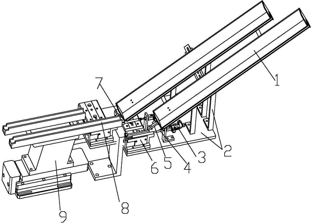
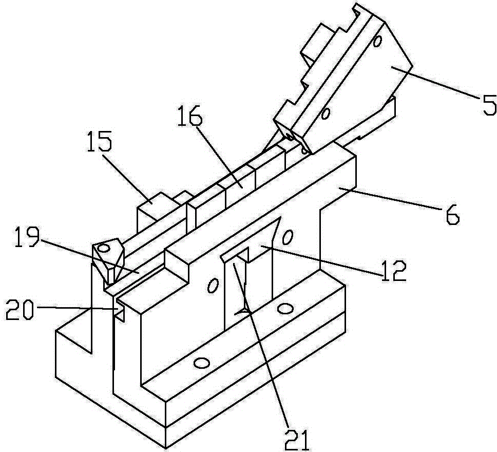
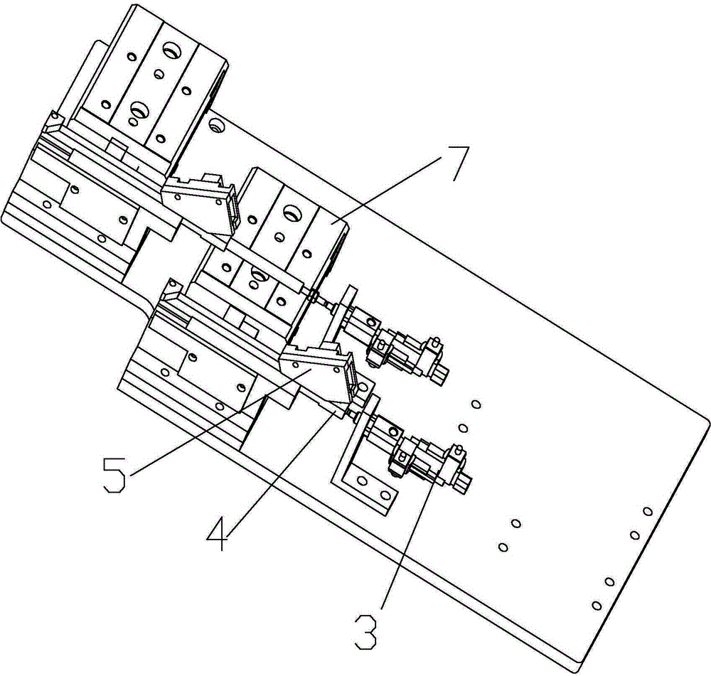
[0027] like figure 1 As shown, the pipe charging and feeding device of the present invention includes a frame 2, and an unloading mechanism is inclined on the frame 2, and the unloading mechanism can be as figure 1 As shown in the hopper 1, the inclination angle of the hopper 1 can be set and adjusted according to actual usage conditions. A discharge channel is provided on the discharge mechanism, and a limit block 5 is arranged obliquely outside the lower end of the discharge channel, and a component position adjustment channel facing the discharge channel is arranged in the limit block 5 . Tube loading can slide down to the limit block 5 along the above-mentioned unloading channel, and then each component slides out along the material tube and enters the component position adjustment channel in the limit block 5 . The component position adj...


PUM


Abstract

The invention discloses a feed device for tube-loaded materials. The feed device for the tube-loaded materials is good in universality and interchangeability, capable of feeding for various components, small in floor space, capable of being stored and used independently and convenient to install, use and maintain. The feed device for the tube-loaded materials comprises a rack. A discharging mechanism is arranged on the rack in an inclined mode. A discharging channel is arranged on the discharging mechanism. A limiting block is arranged on the outer side of the lower end of the discharging channel in an inclined mode. A component position-adjusting channel which faces toward the discharging channel is arranged in the limiting block and comprises a limiting block pin channel which is used for being passed by a component pin and a limiting block body channel which is arranged above the limiting block pin channel and used for being passed by a component body. A cutting shaping mechanism which is installed on the rack is arranged below the component position-adjusting channel. A straight-shocking guide rail which is installed on a straight-shocking base is arranged outside the cutting shaping mechanism.

Description

technical field [0001] The invention relates to the field of feeding devices for electronic components, in particular to a feeding device for tube charging. Background technique [0002] When the electronics industry inserts PCB boards, it is often necessary to send various electronic components into the processing center, and then insert the electronic components into the PCB board through the processing center. Electronic components generally include a body and pins arranged under the body. When electronic components leave the factory, the length of their pins is often too long, and the pins are generally in a vertical state. Therefore, before inserting electronic components into the PCB board, it is generally necessary to cut the length of the pins, and in some cases, it is necessary to bend the cut pins. The cut and bent components need to be sent to the processing center through the corresponding mechanism and installed on the corresponding PCB board. In the prior ar...

Claims


Application Information

Patent Timeline
IPC IPC(8): H05K13/02
Inventor 杨春杨龙何长建唐飞贾统斌
Owner 广东华技达精密机械有限公司
Why Eureka
Try Eureka