Electromagnetic turbine

A generator and current technology, applied in synchronous generators, wind power generation, synchronous motors with stationary armatures and rotating magnets, etc., can solve the problems of low efficiency of unipolar generators

Inactive Publication Date: 2015-07-22
HERON ENERGY
View PDF4 Cites 2 Cited by
  • Summary
  • Abstract
  • Description
  • Claims
  • Application Information

AI Technical Summary

Problems solved by technology

[0008] Despite multiple advances in design and materials since Faraday's original demonstration, unipolar generators have generally long been considered very inefficient

Method used


Image

  • Electromagnetic turbine
  • Electromagnetic turbine
  • Electromagnetic turbine

Examples


Embodiment Construction

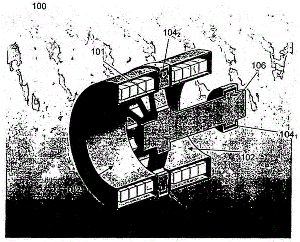
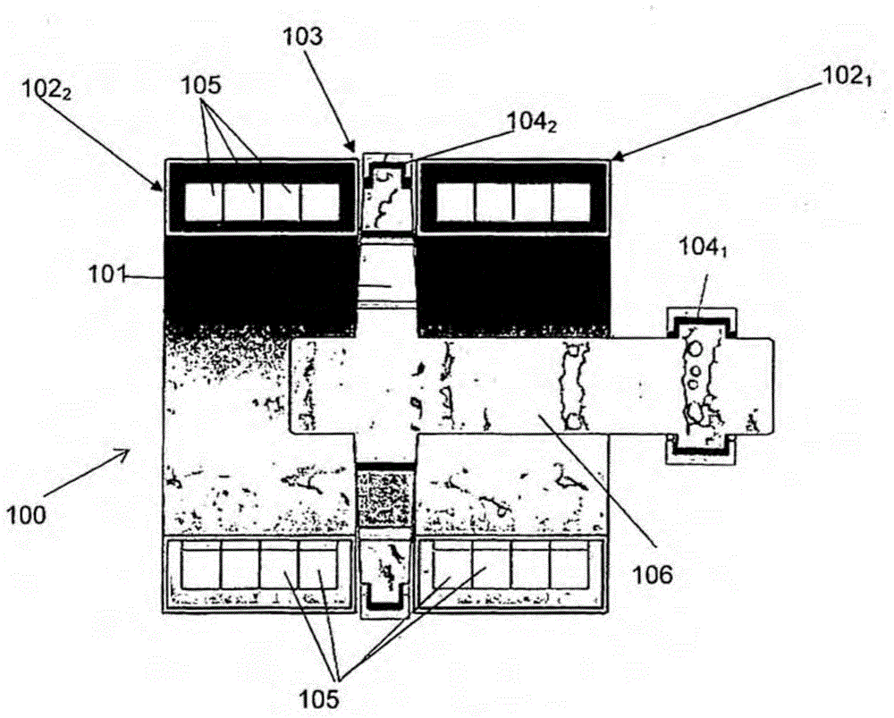
[0224] See Figure 1A , shows a structure that can be adopted by the electromagnetic turbine generator used as the generator 100 according to an embodiment of the present invention. The basic layout of a generator consists of a conductive disk 101 rotating in a magnetic field oriented in the direction of the disk's axis of rotation. The magnetic field in the basic layout is generated by two superconducting solenoids 102 passing a DC current in the same direction 1 、102 2 produce, superconducting solenoid 102 1 、102 2 separated by a gap 103 . The rotor 101 is positioned in the center of this gap 103 for the placement of liquid metal brushes 104 2 And the establishment of the field-free zone. As the disc 101 rotates under the action of an external power source, the inner liquid metal current collector 104 1 with the outer liquid metal current collector 104 2 voltage is established between. When the arrangement is connected to a suitable electric load, current flows from ...


PUM


Abstract

A generator including a first magnetic assembly and a second magnetic assembly wherein the first and second magnetic assemblies are arranged in parallel for the production of a magnetic field and a null magnetic field region, a rotor positioned between the first and second magnetic assemblies the rotor being coupled to a drive shaft extending through the first and second magnetic assemblies wherein a portion of the rotor is positioned in the null field region, a least one current transfer mechanism coupled to the rotor in the null field region and at least one current transfer mechanism coupled to the shaft, a drive mechanism attached to the shaft, whereby actuation of the drive mechanism causes rotation of the rotor in the magnetic field to produce a electric potential between the first and second current transfer mechanisms.

Description

technical field [0001] The present invention relates to electromagnetic turbine generators. In particular, but not exclusively, the invention relates to electromagnetic turbine generators for generating electricity. Background technique [0002] A fundamental principle of physics is the relationship between electricity and magnetism. This relationship was first observed in the mid-19th century, when it was noted that a current passing through a simple conductor bar induced a magnetic field perpendicular to the direction of the current flow. As a result of the induced magnetic field, there is a force on each moving charge that makes up the current. The force applied to each moving charge produces a torque on the conductor proportional to the magnetic field. [0003] The fundamental interaction between electric and magnetic fields discussed above is the fundamental scientific principle underpinning electric motors and generators. One of the simplest forms of electrical gen...

Claims


Application Information

Patent Timeline
Patent Type & Authority Applications(China)
IPC IPC(8): H02K7/00H02K16/00H02K31/00H02K55/00
CPCH02K3/28H02K1/12Y02E10/725H02K16/00H02K19/20Y02E40/627H02K13/003H02K47/14H02K55/06H02K7/116H02K7/183H02K31/04H02K47/04Y02E10/72Y02E40/60H02K1/06H02K3/02H02K7/20H02K21/24H02K55/00
Inventor 安特·圭纳约翰·凯尔斯柯尔特·拉波斯戴维·瑟科姆贝托尼·利星顿雷内·福格阿卡迪·马特塞克塞西米罗·保利诺·法比安·吉罗尼莫
Owner HERON ENERGY
Why Eureka
Try Eureka