Movable step type located mold

A step-type, mold technology, used in positioning devices, forming tools, manufacturing tools, etc., can solve problems such as unsmooth stripping, deformation of positioning holes, and blocking of blanks, so as to achieve smooth stripping, avoid friction, and produce low cost effect

Inactive Publication Date: 2015-07-29
DONGGUAN HAOSHUN PRECISION TECH CO LTD
View PDF9 Cites 3 Cited by
  • Summary
  • Abstract
  • Description
  • Claims
  • Application Information

AI Technical Summary

Problems solved by technology

[0002] In the prior art, the internal positioning commonly used in the mold is a fixed type, that is, the internal positioning pins in the mold are fixedly set, and the cooperation between the blank and the internal positioning pins is achieved by socketing the positioning holes of the blanks in the internal positioning. The positioning pin, in the process of stripping, then push the material piece upwards out of the inner positioning pin through the ejector pin, when the ejector pin pushes the material piece upward out of the inner positioning pin, the material positioning hole will be aligned The pin produces friction, so it is easy to cause the positioning hole of the material to be deformed, and in the process of stripping, the material is likely to be stuck, resulting in unsmooth stripping
In addition, when the stripping gap of the mold is too small, this method of pushing the tablet upwards out of the inner positioning pin through the ejector pin may also easily cause the tablet to be stuck, resulting in unsmooth stripping

Method used


Image

  • Movable step type located mold

Examples


Embodiment 2

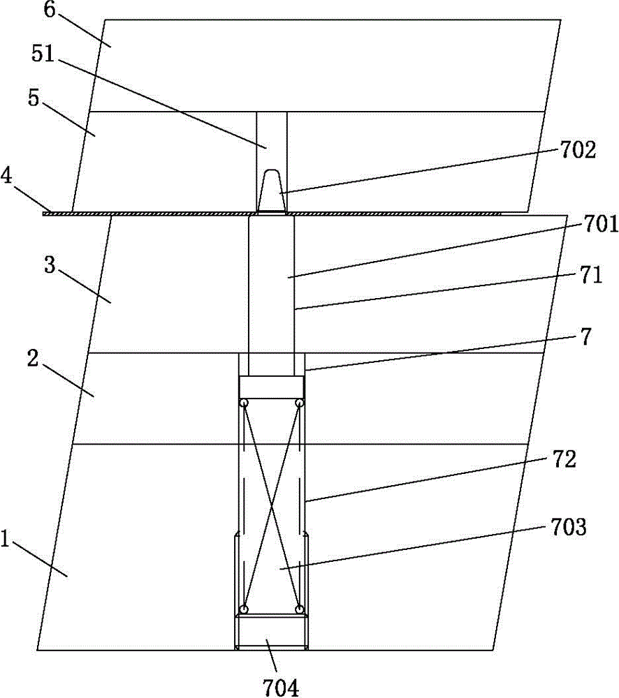
[0035] Embodiment 2 of a movable stepped positioning mold of the present invention, the difference between this embodiment and Embodiment 1 is that in this embodiment, the number of positioning and ejection mechanisms 7 is set to two, and the tablet 4 is set There are two positioning holes, and the bosses 702 of the two positioning ejection mechanisms 7 are respectively sleeved in the corresponding two positioning holes. The two positioning and ejecting mechanisms 7 drive the tablet 4 to move at the same time, which can make the tablet 4 stable and smooth during the stripping process. Other structures and working principles of this embodiment are the same as those of Embodiment 1, and will not be repeated here.

[0036] Example 3 。

Embodiment 3

[0037] Embodiment 3 of a movable stepped positioning mold of the present invention, the difference between this embodiment and Embodiment 1 is that in this embodiment, the number of positioning and ejection mechanisms 7 is set to four, and the blank 4 is set to There are four positioning holes, and the bosses 702 of the four positioning ejection mechanisms 7 are respectively sleeved in the corresponding four positioning holes. The four positioning and ejecting mechanisms 7 drive the tablet 4 to move at the same time, which can make the stripping process of the tablet 4 more stable and smoother. Other structures and working principles of this embodiment are the same as those of Embodiment 1, and will not be repeated here.


PUM


Abstract

The invention relates to the technical field of display screen back panel mold structures, in particular to a movable step type located mold. A locating ejection mechanism comprises a step type internal locating pin and an ejection mechanism which is connected with the step type internal locating pin and can drive the step type internal locating pin to telescope; the step type internal locating pin comprises a pin main body and a boss arranged at one end of the pin main body, and the diameter of the boss is smaller than that of the pin main body; a locating hole is formed in a material sheet, and the material sheet sleeves the boss through the locating hole. The ejection mechanism directly drives the telescopic motion of the step type internal locating pin, and the step type internal locating pin drives the material sheet to move while telescoping, so that the circumstance in the prior art that the locating hole of the material sheet can be in friction with the internal locating pin and then easily causes the deformation of the locating hole of the material sheet is avoided, thus, the circumstance that the material sheet is easily stuck during demolding can be avoided, and thus, the movable step type located mold has the advantage of smoothness in demolding.

Description

technical field [0001] The invention relates to the technical field of mold structure for a display screen backplane, in particular to a mould for movable step positioning. Background technique [0002] In the prior art, the internal positioning commonly used in the mold is a fixed type, that is, the internal positioning pins in the mold are fixedly set, and the cooperation between the blank and the internal positioning pins is achieved by socketing the positioning holes of the blanks in the internal positioning. The positioning pin, in the process of stripping, then push the material piece upwards out of the inner positioning pin through the ejector pin, when the ejector pin pushes the material piece upward out of the inner positioning pin, the material positioning hole will be aligned The pin produces friction, so it is easy to cause the positioning hole of the material to be deformed, and then in the process of stripping, the material is easily stuck, thereby causing the ...

Claims


Application Information

Patent Timeline
IPC IPC(8): B21D37/10B21D37/12B21D43/00B21D45/02
CPCB21D37/12B21D43/003B21D45/04
Inventor 郝建广全洪杰刘博涂燕娇詹海潮程姣
Owner DONGGUAN HAOSHUN PRECISION TECH CO LTD
Why Eureka
Try Eureka